High-Torque Transmission Solutions for the UK’s Renewable Energy Frontier
The UK is a global giant in wind energy, particularly in harsh, high-salinity environments like the North Sea and the Irish Sea. For engineers managing large offshore wind farms like Dogg Beach or Hornsey, the drive system is the heart of the turbine. UK pto-drive-shafts.com Ltd., located in the heart of East Anglia (Berry St Edmunds, Suffolk), understands that an industrial driveshaft is more than just a rotating pipe; it’s a meticulously designed bridge that must withstand up to 25 years of continuous cyclic loads, salt spray corrosion, and extreme torsional vibrations.
The Engineering Reality: Navigating the Nacelle’s Drivetrain
Within the confined space of a 100-meter radius above the turbulent sea, inside the turbine nacelle, the transmission system converts the low-speed, high-torque rotation of the blades into the high-speed rotation of the generator. This conversion requires two different drive shafts: a low-speed main shaft and a high-speed shaft (HSS).
1. The Main Shaft (Low-Speed / High-Torque)
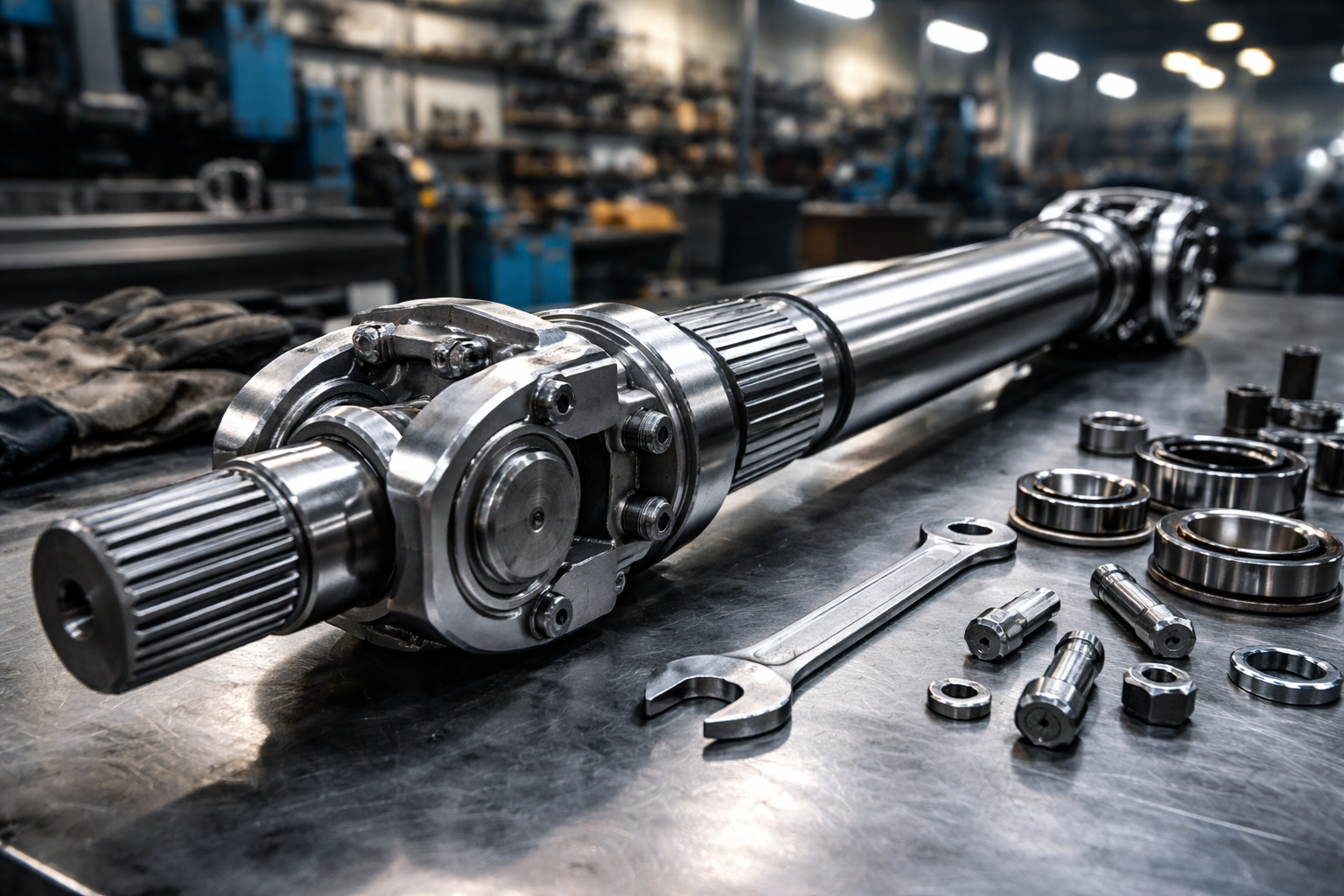
The main shaft is the primary load-bearing component. It must withstand the weight of the hub and blades—typically exceeding 100 tons—while also resisting the enormous thrust and bending moments generated by strong winds. In modern megawatt-class wind turbines (6 MW to 15 MW), we use high-grade 42CrMo4 alloy steel, which undergoes deep quenching and tempering to ensure core toughness and prevent fatigue cracking over millions of cycles.
2. The High-Speed Shaft (HSS) & The Necessity of Insulation
Connecting the gearbox output to the generator, the HSS operates at significantly higher RPMs. The primary engineering challenge here is Electrical Pitting. Generators often produce parasitic “bearing currents” or shaft currents. If these currents travel through a metal coupling into the gearbox, they destroy the oil film on the bearings, leading to catastrophic failure.
Expert Engineering Note: The Suffolk Field Report
“In my 14 years of servicing turbines off the coast of Lowestoft and Great Yarmouth, the most frequent ‘invisible’ killer I’ve seen isn’t mechanical wear—it’s electrical erosion. In 2022, we inspected a site where standard couplings were failing every 18 months. By integrating our Glass Fiber Reinforced Plastic (GFRP) insulated drive shafts, we provided a 5kV dielectric barrier. Two years later, those gearboxes are running at 100% health with zero electrical pitting in the bearings. If you aren’t insulating your HSS, you’re essentially waiting for a lightning strike to ground through your gears.” — Senior Mechanical Engineer, UK pto-drive-shafts.com
Core Technology Summary: 32 Critical Technical Parameters
For procurement officers and lead engineers, the following matrix defines our wind-sector industrial drive shafts.
Local Industrial Landscape: Suffolk and The UK’s “Wind Coast”
Operating from Bury St Edmunds (IP32 7LX), we are strategically positioned to serve the UK’s most critical wind energy hubs. The proximity to the ports of Lowestoft, Felixstowe, and Great Yarmouth allows our rapid-response teams to deliver replacement shafts and engineering support within hours, not days.
-
East Anglia Hub: Specializing in offshore maintenance for the Norfolk and Suffolk coasts.
-
Humber Region: Supporting the massive installations managed from Grimsby and Hull.
-
Scotland (Aberdeen/Leith): Providing heavy-duty shafts for deep-water floating wind foundations.
In the UK, the Supply of Machinery (Safety) Regulations 2008 and the Work Equipment (PUWER) standards mandate that all rotating transmission components must be adequately guarded and failure-resistant. Our shafts are designed not just for performance, but for total compliance with UK Health and Safety Executive (HSE) requirements.
Global Brand Compatibility & Engineering Standards
Note: The following names are used for technical cross-reference only. UK pto-drive-shafts.com Co.,Ltd. is an independent manufacturer of high-performance alternative components.
Our industrial shafts are engineered to be high-durability replacements for, or compatible with, the systems found in:
-
Vestas™ & Siemens Gamesa™ Drivetrains.
-
GKN™ Industrial Series (Technical reference only).
-
Comer Industries™ Gearbox Connections (Note: UK pto-drive-shafts.com Co.,Ltd is an independent manufacturer).
-
Voith™ / GWB™ Large Scale Industrial Drives.
By utilizing advanced metallurgical analysis, we often exceed the original OEM specifications, particularly in terms of maritime corrosion resistance (C5-M standards) which are vital for the UK’s specific coastal humidity.
Integrated Power Transmission: The Role of the Wind Turbine Gearbox
A drive shaft is only as effective as the gearbox it connects to. At UK pto-drive-shafts.com Co.,Ltd., we specialize in the “Total Drivetrain” approach. We don’t just supply the shaft; we manufacture the high-precision planetary and helical gearboxes that sit at the core of the nacelle.
The Gearbox Engineering Challenge
In a wind turbine, the gearbox is the most complex and stressed component. It must take the 10-15 RPM of the massive rotor and step it up to approximately 1500 RPM for the generator. This 100:1 ratio is typically achieved through a multi-stage process: two stages of planetary gears followed by a single stage of parallel (helical) gears.
1. The Planetary Advantage: To handle the extreme torque of a 10MW turbine, planetary gears are essential because they distribute the load across multiple “planets,” reducing the stress on individual teeth. Our gearboxes utilize Carburized and Ground Gearing with a surface hardness of 58-62 HRC. This ensures the teeth can withstand the contact fatigue (pitting) that often plagues lower-quality units.
2. Lubrication and Cooling: A wind gearbox generates immense heat. Our integrated systems feature forced-feed lubrication with redundant pump systems. We use advanced synthetic oils with high viscosity indices to ensure that whether it’s a freezing winter night in the Highlands or a warm summer day in Kent, the oil film remains intact. Our gearboxes include integrated particle monitoring systems—real-time sensors that detect metallic debris, allowing for “Predictive Maintenance” before a minor bearing wear becomes a catastrophic failure.
3. Advanced Materials & Housing: The gearbox housing is cast from high-grade ductile iron (GJS-400-18-LT), specifically chosen for its low-temperature impact toughness. This is critical for turbines in the North Sea, where the metal must remain resilient and not become brittle in sub-zero maritime storms.
4. Compatibility with Industrial Drive Shafts: The output shaft of our gearboxes is designed with a Shrink Disc (Amman type) connection. This creates a friction-locked, zero-backlash joint with the eixo cardan. Unlike traditional keyed shafts, which can develop “fretting corrosion” under the reversing loads of a wind turbine, a shrink-disc connection remains tight for the life of the machine.
Failure Analysis & Reliability: Why Drive Shafts Fail and How We Fix It
Scenario: Resonance and Vibration In a site near the Dogger Bank, a series of turbines experienced recurring U-joint failure. Upon investigation, our team found that the structural frequency of the nacelle frame was aligning with the rotational frequency of the high-speed shaft at 1800 RPM. This “Critical Speed” was causing the shaft to whip.
-
A solução: We redesigned the shaft with a larger diameter but thinner wall thickness. This shifted the “Critical Speed” 30% higher, well out of the operating range. We also added elastomeric dampening to the flange mounts to absorb residual harmonics.
Scenario: Salt-Mist Ingress Standard industrial grease often emulsifies when exposed to the high-salinity air of the UK coast. Once the grease loses its lubricity, needle bearings in the U-joint overheat and seize.
-
A solução: We utilize Triple-Lip Sealing technology and marine-specific synthetic greases that are “water-repellent” and maintain a chemical barrier against chloride ions.
FAQ: Technical Insights for Drivetrain Engineers
-
Q: Why choose a Cardan shaft over a rigid coupling in a wind turbine?
-
A: A nacelle is not a rigid structure. Under wind load, the frame flexes. A rigid coupling would transfer these bending forces directly into the gearbox bearings, leading to premature failure. A Cardan shaft accommodates this “misalignment” while maintaining constant torque.
-
-
Q: How often should the HSS be inspected?
-
A: In the UK offshore sector, we recommend a visual inspection every 6 months and a full ultrasonic testing of the welds every 2 years.
-
-
Q: Can your shafts be retrofitted to older Senvion or REpower turbines?
-
A: Yes. We specialize in “Drop-in Replacements” that match the original flange dimensions but utilize modern 2025-spec materials and coatings.
-
-
Q: What is the lead time for a custom-length industrial shaft in the UK?
-
A: For emergency breakdowns, our Bury St Edmunds facility can often provide a solution within 48-72 hours, depending on material availability.
-
The Path Forward: UK Wind Energy News & Updates
-
Dogger Bank A First Power: The UK’s flagship project has begun exporting power. We are providing ongoing support for the auxiliary drive systems used in the installation vessels.
-
Floating Wind Initiatives: The Crown Estate has identified new areas for floating wind in the Celtic Sea. This will require new generations of extra-long, lightweight carbon-fiber drive shafts to handle the increased motion of floating platforms.
-
Grid Stability Focus: New UK regulations require turbines to have “Low Voltage Ride Through” capabilities. Our insulated drive shafts help protect delicate generator electronics during these grid-fault events.
Final Engineering Verdict
At UK pto-drive-shafts.com Co.,Ltd., we don’t just sell parts; we provide the mechanical certainty that your turbine will keep turning through the toughest British winters. Whether you are managing a 20-year-old onshore farm in Cornwall or the latest offshore behemoths, our engineering team in Suffolk is ready to optimize your drivetrain.
Contact Our Engineering Team: UK pto-drive-shafts.com Co.,Ltd. Bury St Edmunds, Suffolk IP32 7LX, UK Email: [email protected]
Editado por gzl


