Opis produktu
Opis produktu
Our compay always insists high-quality standard producing and continually improve ourselves since the very beginning of company’s establishment, we always contribute to make perfect combination of equipment and technology, made the high stable quality.
| Part Name | CV AXLE |
| Marka | AUTOJET/AAE/STOP/ as customers requirements |
| Aplikacja | Auto Transmission System |
| car maker | All AMERICAN,BIRTITSH, JAPANESS, and KOREAN |
| Placement on Vehicle | Right/ Left |
| Tworzywo | Iron/Steel |
| Gwarancja | 12 Months |
| Sample | Dostępny |
| Price | Negotiable |
| Place of origin | Any Chinese port |
| Delivery time | 30-45 days after confirmed |
| Packing | Processional |
| MOQ | 100 PCS |
| Payment | L/C,T/T,Western Union,PayPal |
Szczegółowe zdjęcia
Main Products
Profil firmy
ZheJiang CZPT Macinery equipments is a new developing manufacturing company. Producing Auto parts production lines. As well we have 15 years of exporting auto parts for all automotive products. As after market supplies. Our main products are SHOCK ABSORBING, POWER STEERING SYSTEMS, SUSPENSION, CV AXLE, CV JONTS, and AUTO LIGHTS. We have our own brands and we do customize brand for customers requirements. Our products are produced under quality control team. Two advantage we offer; Genuine parts quality and After market price best value parts. Our products has 98% warranty for 1 year form date of use. Some items are warranty per KM 98% means we accept a claim if the damaged parts more then 2% of the quantity up to manufacturing fault for After Sales Service We have different solutions for different customers. Our company is sincerely willing to cooperate with enterprises from all over the world in order to realize a CZPT situation since the trend of economic globalization has developed with an irresistible force.
Our Factories
Opakowanie i wysyłka
Często zadawane pytania
1.Are you a factory or a trading company ?
We are a factory and trading company at the same time.
2.Where is your company located ? How can I visit there ?
Our company is located in HangZhou, all clients, from home and abroad, are warmly welcomed to visit us .
3.How about the quality of the products ?
Our products are of high quality and we have registered and reputable brands.
4.What’s the MOQ for each items ?
100 pieces.
5.Could we supply samples ?
We offer samples,but the samples should be paid.
6.What’s the delivery time ?
30-45 working days after confirmed
7.What’s our shipping ways ?
We can provide different types of shipping such as sea, air, and land.
/* 22 stycznia 2571 19:08:37 */!function(){function s(e,r){var a,o={};try{e&&e.split(„”,).forEach(function(e,t){e&&(a=e.match(/(.*?):(.*)$/))&&1
| Serwis posprzedażowy: | 1 Year |
|---|---|
| Stan : schorzenie: | Nowy |
| Color: | Black |
| Orzecznictwo: | ISO, IATF-16949 |
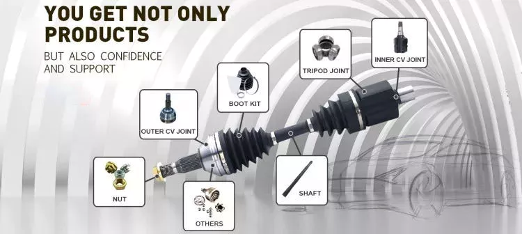
| Typ: | CV Axle |
| Application Brand: | Toyota |
| Personalizacja: |
Dostępny
| Spersonalizowane żądanie |
|---|
W jaki sposób wały napędowe zapewniają efektywne przenoszenie mocy przy jednoczesnym zachowaniu równowagi?
Wały napędowe wykorzystują różne mechanizmy, aby zapewnić efektywne przenoszenie mocy przy jednoczesnym zachowaniu równowagi. Efektywne przenoszenie mocy odnosi się do zdolności wału napędowego do przenoszenia mocy obrotowej ze źródła (takiego jak silnik) do napędzanych elementów (takich jak koła lub maszyny) przy minimalnej stracie energii. Wyważanie natomiast polega na minimalizacji drgań i wyeliminowaniu nierównomiernego rozkładu masy, który może powodować zakłócenia podczas pracy. Oto wyjaśnienie, w jaki sposób wały napędowe zapewniają zarówno efektywne przenoszenie mocy, jak i równowagę:
1. Wybór materiałów:
Dobór materiałów na wały napędowe ma kluczowe znaczenie dla zachowania równowagi i zapewnienia efektywnego przenoszenia mocy. Wały napędowe są zazwyczaj wykonane z materiałów takich jak stal lub stopy aluminium, wybieranych ze względu na ich wytrzymałość, sztywność i trwałość. Materiały te charakteryzują się doskonałą stabilnością wymiarową i wytrzymują obciążenia momentem obrotowym występujące podczas pracy. Dzięki zastosowaniu wysokiej jakości materiałów, wały napędowe minimalizują odkształcenia, ugięcie i zaburzenia równowagi, które mogłyby zaburzyć przenoszenie mocy i generować wibracje.
2. Zagadnienia projektowe:
Konstrukcja wału napędowego odgrywa istotną rolę zarówno w efektywności przenoszenia mocy, jak i w równowadze. Wały napędowe są projektowane tak, aby miały odpowiednie wymiary, w tym średnicę i grubość ścianek, aby przenosić przewidywane obciążenia momentem obrotowym bez nadmiernych ugięcia i wibracji. Projekt uwzględnia również takie czynniki, jak długość wału napędowego, liczba i rodzaj połączeń (takich jak przeguby krzyżakowe lub przeguby homokinetyczne) oraz zastosowanie obciążników wyważających. Dzięki starannemu zaprojektowaniu wału napędowego producenci mogą osiągnąć optymalną efektywność przenoszenia mocy, minimalizując jednocześnie ryzyko wystąpienia wibracji wywołanych brakiem równowagi.
3. Techniki równoważenia:
Równowaga ma kluczowe znaczenie dla wałów napędowych, ponieważ każda jej nierównowaga może powodować wibracje, hałas i przyspieszone zużycie. Aby utrzymać równowagę, wały napędowe poddawane są różnym technikom wyważania w procesie produkcji. Stosowane są metody wyważania statycznego i dynamicznego, aby zapewnić równomierny rozkład masy na wale napędowym. Wyważanie statyczne polega na dodawaniu przeciwwag w określonych miejscach w celu zrównoważenia wszelkich nierównowag masy. Wyważanie dynamiczne odbywa się poprzez obracanie wału napędowego z dużą prędkością i pomiar drgań. W przypadku wykrycia nierównowagi, wprowadzane są dodatkowe regulacje w celu uzyskania równowagi. Te techniki wyważania pomagają zminimalizować wibracje i zapewnić płynną pracę wału napędowego.
4. Przeguby uniwersalne i przeguby homokinetyczne:
Wały napędowe często zawierają przeguby krzyżakowe (U-joints) lub przeguby homokinetyczne (CV), które kompensują niewspółosiowość i utrzymują równowagę podczas pracy. Przeguby krzyżakowe to elastyczne przeguby, które umożliwiają ruch kątowy między wałami. Są one zazwyczaj stosowane w zastosowaniach, w których wał napędowy pracuje pod zmiennym kątem. Przeguby homokinetyczne natomiast są zaprojektowane tak, aby utrzymywać stałą prędkość obrotową i są powszechnie stosowane w pojazdach z napędem na przednie koła. Dzięki zastosowaniu tych przegubów, wały napędowe mogą kompensować niewspółosiowość, zmniejszać naprężenia na wale i minimalizować drgania, które mogą negatywnie wpływać na wydajność przenoszenia mocy i równowagę.
5. Konserwacja i przeglądy:
Regularna konserwacja i przeglądy wałów napędowych są niezbędne dla zapewnienia efektywnego przenoszenia mocy i równowagi. Okresowe kontrole zużycia, uszkodzeń lub niewspółosiowości mogą pomóc w identyfikacji wszelkich problemów, które mogą wpływać na działanie wału napędowego. Smarowanie połączeń i prawidłowe dokręcanie śrub są również kluczowe dla utrzymania optymalnej pracy. Przestrzeganie zalecanych procedur konserwacyjnych pozwala na szybką reakcję na wszelkie nieprawidłowości w równowadze lub niesprawności, zapewniając ciągłe efektywne przenoszenie mocy i równowagę.
Podsumowując, wały napędowe zapewniają efektywne przenoszenie mocy przy jednoczesnym zachowaniu równowagi dzięki starannemu doborowi materiałów, przemyślanej konstrukcji, technikom wyważania oraz zastosowaniu elastycznych połączeń. Dzięki optymalizacji tych czynników, wały napędowe mogą płynnie i niezawodnie przenosić moc obrotową, minimalizując straty energii i wibracje, które mogą wpływać na wydajność i żywotność.
Can drive shafts be customized for specific vehicle or equipment requirements?
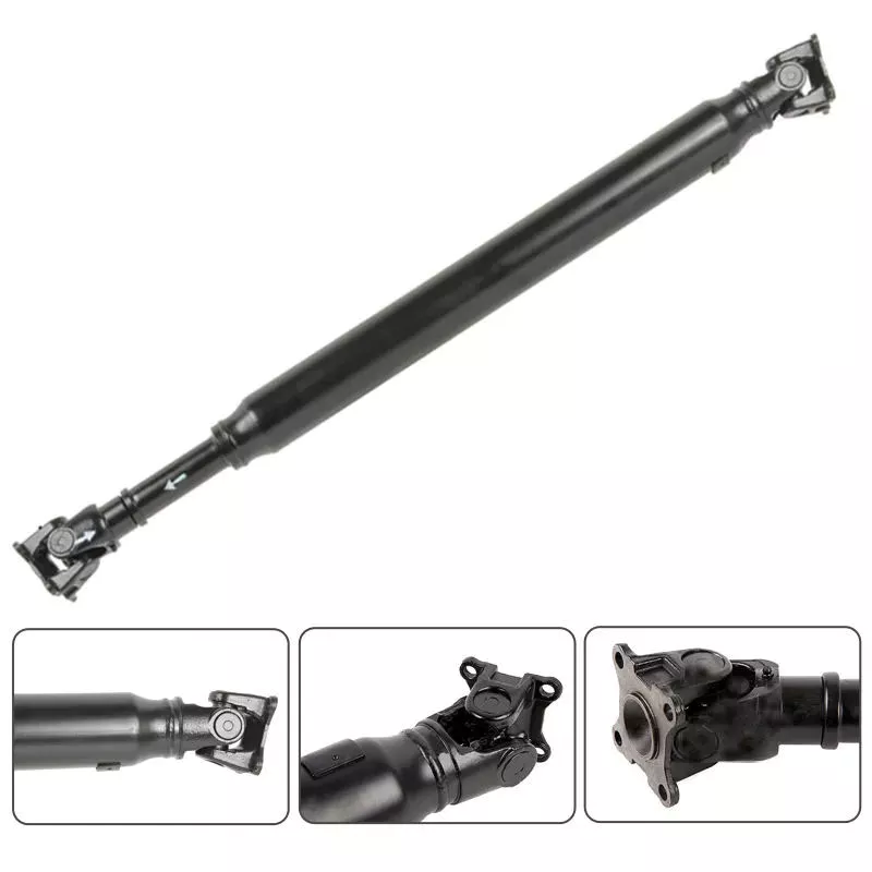
Yes, drive shafts can be customized to meet specific vehicle or equipment requirements. Customization allows manufacturers to tailor the design, dimensions, materials, and other parameters of the drive shaft to ensure compatibility and optimal performance within a particular vehicle or equipment. Here’s a detailed explanation of how drive shafts can be customized:
1. Dimensional Customization:
Drive shafts can be customized to match the dimensional requirements of the vehicle or equipment. This includes adjusting the overall length, diameter, and spline configuration to ensure proper fitment and clearances within the specific application. By customizing the dimensions, the drive shaft can be seamlessly integrated into the driveline system without any interference or limitations.
2. Material Selection:
The choice of materials for drive shafts can be customized based on the specific requirements of the vehicle or equipment. Different materials, such as steel alloys, aluminum alloys, or specialized composites, can be selected to optimize strength, weight, and durability. The material selection can be tailored to meet the torque, speed, and operating conditions of the application, ensuring the drive shaft’s reliability and longevity.
3. Joint Configuration:
Drive shafts can be customized with different joint configurations to accommodate specific vehicle or equipment requirements. For example, universal joints (U-joints) may be suitable for applications with lower operating angles and moderate torque demands, while constant velocity (CV) joints are often used in applications requiring higher operating angles and smoother power transmission. The choice of joint configuration depends on factors such as operating angle, torque capacity, and desired performance characteristics.
4. Torque and Power Capacity:
Customization allows drive shafts to be designed with the appropriate torque and power capacity for the specific vehicle or equipment. Manufacturers can analyze the torque requirements, operating conditions, and safety margins of the application to determine the optimal torque rating and power capacity of the drive shaft. This ensures that the drive shaft can handle the required loads without experiencing premature failure or performance issues.
5. Balancing and Vibration Control:
Drive shafts can be customized with precision balancing and vibration control measures. Imbalances in the drive shaft can lead to vibrations, increased wear, and potential driveline issues. By employing dynamic balancing techniques during the manufacturing process, manufacturers can minimize vibrations and ensure smooth operation. Additionally, vibration dampers or isolation systems can be integrated into the drive shaft design to further mitigate vibrations and enhance overall system performance.
6. Integration and Mounting Considerations:
Customization of drive shafts takes into account the integration and mounting requirements of the specific vehicle or equipment. Manufacturers work closely with the vehicle or equipment designers to ensure that the drive shaft fits seamlessly into the driveline system. This includes adapting the mounting points, interfaces, and clearances to ensure proper alignment and installation of the drive shaft within the vehicle or equipment.
7. Collaboration and Feedback:
Manufacturers often collaborate with vehicle manufacturers, OEMs (Original Equipment Manufacturers), or end-users to gather feedback and incorporate their specific requirements into the drive shaft customization process. By actively seeking input and feedback, manufacturers can address specific needs, optimize performance, and ensure compatibility with the vehicle or equipment. This collaborative approach enhances the customization process and results in drive shafts that meet the exact requirements of the application.
8. Compliance with Standards:
Customized drive shafts can be designed to comply with relevant industry standards and regulations. Compliance with standards, such as ISO (International Organization for Standardization) or specific industry standards, ensures that the customized drive shafts meet quality, safety, and performance requirements. Adhering to these standards provides assurance that the drive shafts are compatible and can be seamlessly integrated into the specific vehicle or equipment.
In summary, drive shafts can be customized to meet specific vehicle or equipment requirements through dimensional customization, material selection, joint configuration, torque and power capacity optimization, balancing and vibration control, integration and mounting considerations, collaboration with stakeholders, and compliance with industry standards. Customization allows drive shafts to be precisely tailored to the needs of the application, ensuring compatibility, reliability, and optimal performance.
Can you explain the different types of drive shafts and their specific applications?
Drive shafts come in various types, each designed to suit specific applications and requirements. The choice of drive shaft depends on factors such as the type of vehicle or equipment, power transmission needs, space limitations, and operating conditions. Here’s an explanation of the different types of drive shafts and their specific applications:
1. Solid Shaft:
A solid shaft, also known as a one-piece or solid-steel drive shaft, is a single, uninterrupted shaft that runs from the engine or power source to the driven components. It is a simple and robust design used in many applications. Solid shafts are commonly found in rear-wheel-drive vehicles, where they transmit power from the transmission to the rear axle. They are also used in industrial machinery, such as pumps, generators, and conveyors, where a straight and rigid power transmission is required.
2. Tubular Shaft:
Tubular shafts, also called hollow shafts, are drive shafts with a cylindrical tube-like structure. They are constructed with a hollow core and are typically lighter than solid shafts. Tubular shafts offer benefits such as reduced weight, improved torsional stiffness, and better damping of vibrations. They find applications in various vehicles, including cars, trucks, and motorcycles, as well as in industrial equipment and machinery. Tubular drive shafts are commonly used in front-wheel-drive vehicles, where they connect the transmission to the front wheels.
3. Constant Velocity (CV) Shaft:
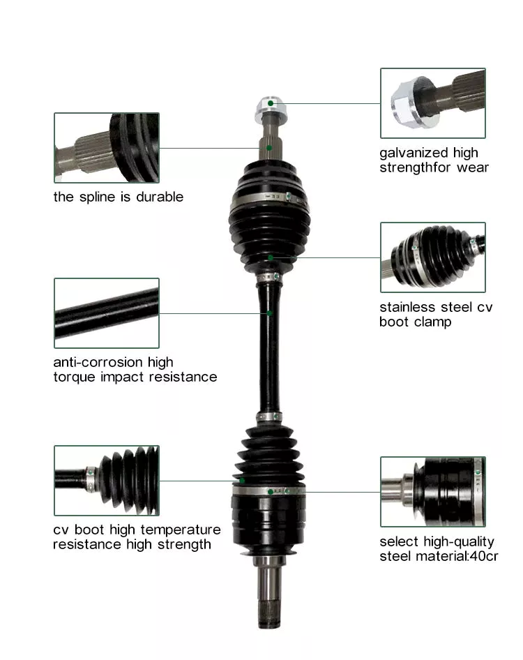
Constant Velocity (CV) shafts are specifically designed to handle angular movement and maintain a constant velocity between the engine/transmission and the driven components. They incorporate CV joints at both ends, which allow flexibility and compensation for changes in angle. CV shafts are commonly used in front-wheel-drive and all-wheel-drive vehicles, as well as in off-road vehicles and certain heavy machinery. The CV joints enable smooth power transmission even when the wheels are turned or the suspension moves, reducing vibrations and improving overall performance.
4. Slip Joint Shaft:
Slip joint shafts, also known as telescopic shafts, consist of two or more tubular sections that can slide in and out of each other. This design allows for length adjustment, accommodating changes in distance between the engine/transmission and the driven components. Slip joint shafts are commonly used in vehicles with long wheelbases or adjustable suspension systems, such as some trucks, buses, and recreational vehicles. By providing flexibility in length, slip joint shafts ensure a constant power transfer, even when the vehicle chassis experiences movement or changes in suspension geometry.
5. Double Cardan Shaft:
A double Cardan shaft, also referred to as a double universal joint shaft, is a type of drive shaft that incorporates two universal joints. This configuration helps to reduce vibrations and minimize the operating angles of the joints, resulting in smoother power transmission. Double Cardan shafts are commonly used in heavy-duty applications, such as trucks, off-road vehicles, and agricultural machinery. They are particularly suitable for applications with high torque requirements and large operating angles, providing enhanced durability and performance.
6. Composite Shaft:
Composite shafts are made from composite materials such as carbon fiber or fiberglass, offering advantages such as reduced weight, improved strength, and resistance to corrosion. Composite drive shafts are increasingly being used in high-performance vehicles, sports cars, and racing applications, where weight reduction and enhanced power-to-weight ratio are critical. The composite construction allows for precise tuning of stiffness and damping characteristics, resulting in improved vehicle dynamics and drivetrain efficiency.
7. PTO Shaft:
Power Take-Off (PTO) shafts are specialized drive shafts used in agricultural machinery and certain industrial equipment. They are designed to transfer power from the engine or power source to various attachments, such as mowers, balers, or pumps. PTO shafts typically have a splined connection at one end to connect to the power source and a universal joint at the other end to accommodate angular movement. They are characterized by their ability to transmit high torque levels and their compatibility with a range of driven implements.
8. Marine Shaft:
Marine shafts, also known as propeller shafts or tail shafts, are specifically designed for marine vessels. They transmit power from the engine to the propeller, enabling propulsion. Marine shafts are usually long and operate in a harsh environment, exposed to water, corrosion, and high torque loads. They are typically made of stainless steel or other corrosion-resistant materials and are designed to withstand the challenging conditions encountered in marine applications.
It’simportant to note that the specific applications of drive shafts may vary depending on the vehicle or equipment manufacturer, as well as the specific design and engineering requirements. The examples provided above highlight common applications for each type of drive shaft, but there may be additional variations and specialized designs based on specific industry needs and technological advancements.


editor by CX 2024-04-16