Productbeschrijving
Productbeschrijving
Our compay always insists high-quality standard producing and continually improve ourselves since the very beginning of company’s establishment, we always contribute to make perfect combination of equipment and technology, made the high stable quality.
| Part Name | CV AXLE |
| Merk | AUTOJET/AAE/STOP/ as customers requirements |
| Sollicitatie | Auto Transmission System |
| car maker | All AMERICAN,BIRTITSH, JAPANESS, and KOREAN |
| Placement on Vehicle | Right/ Left |
| Materiaal | Iron/Steel |
| Garantie | 12 Months |
| Sample | Beschikbaar |
| Price | Negotiable |
| Place of origin | Any Chinese port |
| Delivery time | 30-45 days after confirmed |
| Packing | Processional |
| MOQ | 100 PCS |
| Payment | L/C,T/T,Western Union,PayPal |
Gedetailleerde foto's
Main Products
Bedrijfsprofiel
ZheJiang CZPT Macinery equipments is a new developing manufacturing company. Producing Auto parts production lines. As well we have 15 years of exporting auto parts for all automotive products. As after market supplies. Our main products are SHOCK ABSORBING, POWER STEERING SYSTEMS, SUSPENSION, CV AXLE, CV JONTS, and AUTO LIGHTS. We have our own brands and we do customize brand for customers requirements. Our products are produced under quality control team. Two advantage we offer; Genuine parts quality and After market price best value parts. Our products has 98% warranty for 1 year form date of use. Some items are warranty per KM 98% means we accept a claim if the damaged parts more then 2% of the quantity up to manufacturing fault for After Sales Service We have different solutions for different customers. Our company is sincerely willing to cooperate with enterprises from all over the world in order to realize a CZPT situation since the trend of economic globalization has developed with an irresistible force.
Our Factories
Verpakking en verzending
Veelgestelde vragen
1.Are you a factory or a trading company ?
We are a factory and trading company at the same time.
2.Where is your company located ? How can I visit there ?
Our company is located in HangZhou, all clients, from home and abroad, are warmly welcomed to visit us .
3.How about the quality of the products ?
Our products are of high quality and we have registered and reputable brands.
4.What’s the MOQ for each items ?
100 pieces.
5.Could we supply samples ?
We offer samples,but the samples should be paid.
6.What’s the delivery time ?
30-45 working days after confirmed
7.What’s our shipping ways ?
We can provide different types of shipping such as sea, air, and land.
/* 22 januari 2571 19:08:37 */!function(){function s(e,r){var a,o={};try{e&&e.split(“,”).forEach(function(e,t){e&&(a=e.match(/(.*?):(.*)$/))&&1
| Klantenservice na aankoop: | 1 jaar |
|---|---|
| Voorwaarde: | Nieuw |
| Color: | Black |
| Certificering: | ISO, IATF-16949 |
| Type: | CV Axle |
| Application Brand: | Toyota |
| Aanpassing: |
Beschikbaar
| Aanvraag op maat |
|---|
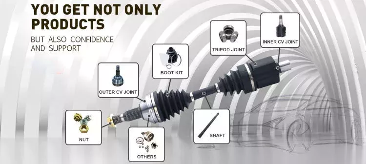
How do drive shafts ensure efficient power transfer while maintaining balance?
Drive shafts employ various mechanisms to ensure efficient power transfer while maintaining balance. Efficient power transfer refers to the ability of the drive shaft to transmit rotational power from the source (such as an engine) to the driven components (such as wheels or machinery) with minimal energy loss. Balancing, on the other hand, involves minimizing vibrations and eliminating any uneven distribution of mass that can cause disturbances during operation. Here’s an explanation of how drive shafts achieve both efficient power transfer and balance:
1. Material Selection:
The material selection for drive shafts is crucial for maintaining balance and ensuring efficient power transfer. Drive shafts are commonly made from materials such as steel or aluminum alloys, chosen for their strength, stiffness, and durability. These materials have excellent dimensional stability and can withstand the torque loads encountered during operation. By using high-quality materials, drive shafts can minimize deformation, flexing, and imbalances that could compromise power transmission and generate vibrations.
2. Design Considerations:
The design of the drive shaft plays a significant role in both power transfer efficiency and balance. Drive shafts are engineered to have appropriate dimensions, including diameter and wall thickness, to handle the anticipated torque loads without excessive deflection or vibration. The design also considers factors such as the length of the drive shaft, the number and type of joints (such as universal joints or constant velocity joints), and the use of balancing weights. By carefully designing the drive shaft, manufacturers can achieve optimal power transfer efficiency while minimizing the potential for imbalance-induced vibrations.
3. Balancing Techniques:
Balance is crucial for drive shafts as any imbalance can cause vibrations, noise, and accelerated wear. To maintain balance, drive shafts undergo various balancing techniques during the manufacturing process. Static and dynamic balancing methods are employed to ensure that the mass distribution along the drive shaft is uniform. Static balancing involves adding counterweights at specific locations to offset any weight imbalances. Dynamic balancing is performed by spinning the drive shaft at high speeds and measuring any vibrations. If imbalances are detected, additional adjustments are made to achieve a balanced state. These balancing techniques help minimize vibrations and ensure smooth operation of the drive shaft.
4. Universal Joints and Constant Velocity Joints:
Drive shafts often incorporate universal joints (U-joints) or constant velocity (CV) joints to accommodate misalignment and maintain balance during operation. U-joints are flexible joints that allow for angular movement between shafts. They are typically used in applications where the drive shaft operates at varying angles. CV joints, on the other hand, are designed to maintain a constant velocity of rotation and are commonly used in front-wheel-drive vehicles. By incorporating these joints, drive shafts can compensate for misalignment, reduce stress on the shaft, and minimize vibrations that can negatively impact power transfer efficiency and balance.
5. Maintenance and Inspection:
Regular maintenance and inspection of drive shafts are essential for ensuring efficient power transfer and balance. Periodic checks for wear, damage, or misalignment can help identify any issues that may affect the drive shaft’s performance. Lubrication of the joints and proper tightening of fasteners are also critical for maintaining optimal operation. By adhering to recommended maintenance procedures, any imbalances or inefficiencies can be addressed promptly, ensuring continued efficient power transfer and balance.
In summary, drive shafts ensure efficient power transfer while maintaining balance through careful material selection, thoughtful design considerations, balancing techniques, and the incorporation of flexible joints. By optimizing these factors, drive shafts can transmit rotational power smoothly and reliably, minimizing energy losses and vibrations that can impact performance and longevity.
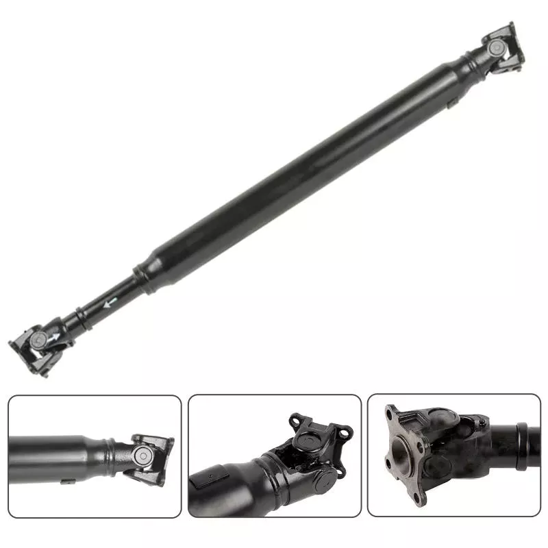
Can drive shafts be customized for specific vehicle or equipment requirements?
Yes, drive shafts can be customized to meet specific vehicle or equipment requirements. Customization allows manufacturers to tailor the design, dimensions, materials, and other parameters of the drive shaft to ensure compatibility and optimal performance within a particular vehicle or equipment. Here’s a detailed explanation of how drive shafts can be customized:
1. Dimensional Customization:
Drive shafts can be customized to match the dimensional requirements of the vehicle or equipment. This includes adjusting the overall length, diameter, and spline configuration to ensure proper fitment and clearances within the specific application. By customizing the dimensions, the drive shaft can be seamlessly integrated into the driveline system without any interference or limitations.
2. Material Selection:
The choice of materials for drive shafts can be customized based on the specific requirements of the vehicle or equipment. Different materials, such as steel alloys, aluminum alloys, or specialized composites, can be selected to optimize strength, weight, and durability. The material selection can be tailored to meet the torque, speed, and operating conditions of the application, ensuring the drive shaft’s reliability and longevity.
3. Joint Configuration:
Drive shafts can be customized with different joint configurations to accommodate specific vehicle or equipment requirements. For example, universal joints (U-joints) may be suitable for applications with lower operating angles and moderate torque demands, while constant velocity (CV) joints are often used in applications requiring higher operating angles and smoother power transmission. The choice of joint configuration depends on factors such as operating angle, torque capacity, and desired performance characteristics.
4. Torque and Power Capacity:
Customization allows drive shafts to be designed with the appropriate torque and power capacity for the specific vehicle or equipment. Manufacturers can analyze the torque requirements, operating conditions, and safety margins of the application to determine the optimal torque rating and power capacity of the drive shaft. This ensures that the drive shaft can handle the required loads without experiencing premature failure or performance issues.
5. Balancing and Vibration Control:
Drive shafts can be customized with precision balancing and vibration control measures. Imbalances in the drive shaft can lead to vibrations, increased wear, and potential driveline issues. By employing dynamic balancing techniques during the manufacturing process, manufacturers can minimize vibrations and ensure smooth operation. Additionally, vibration dampers or isolation systems can be integrated into the drive shaft design to further mitigate vibrations and enhance overall system performance.
6. Integration and Mounting Considerations:
Customization of drive shafts takes into account the integration and mounting requirements of the specific vehicle or equipment. Manufacturers work closely with the vehicle or equipment designers to ensure that the drive shaft fits seamlessly into the driveline system. This includes adapting the mounting points, interfaces, and clearances to ensure proper alignment and installation of the drive shaft within the vehicle or equipment.
7. Collaboration and Feedback:
Manufacturers often collaborate with vehicle manufacturers, OEMs (Original Equipment Manufacturers), or end-users to gather feedback and incorporate their specific requirements into the drive shaft customization process. By actively seeking input and feedback, manufacturers can address specific needs, optimize performance, and ensure compatibility with the vehicle or equipment. This collaborative approach enhances the customization process and results in drive shafts that meet the exact requirements of the application.
8. Compliance with Standards:
Customized drive shafts can be designed to comply with relevant industry standards and regulations. Compliance with standards, such as ISO (International Organization for Standardization) or specific industry standards, ensures that the customized drive shafts meet quality, safety, and performance requirements. Adhering to these standards provides assurance that the drive shafts are compatible and can be seamlessly integrated into the specific vehicle or equipment.
In summary, drive shafts can be customized to meet specific vehicle or equipment requirements through dimensional customization, material selection, joint configuration, torque and power capacity optimization, balancing and vibration control, integration and mounting considerations, collaboration with stakeholders, and compliance with industry standards. Customization allows drive shafts to be precisely tailored to the needs of the application, ensuring compatibility, reliability, and optimal performance.
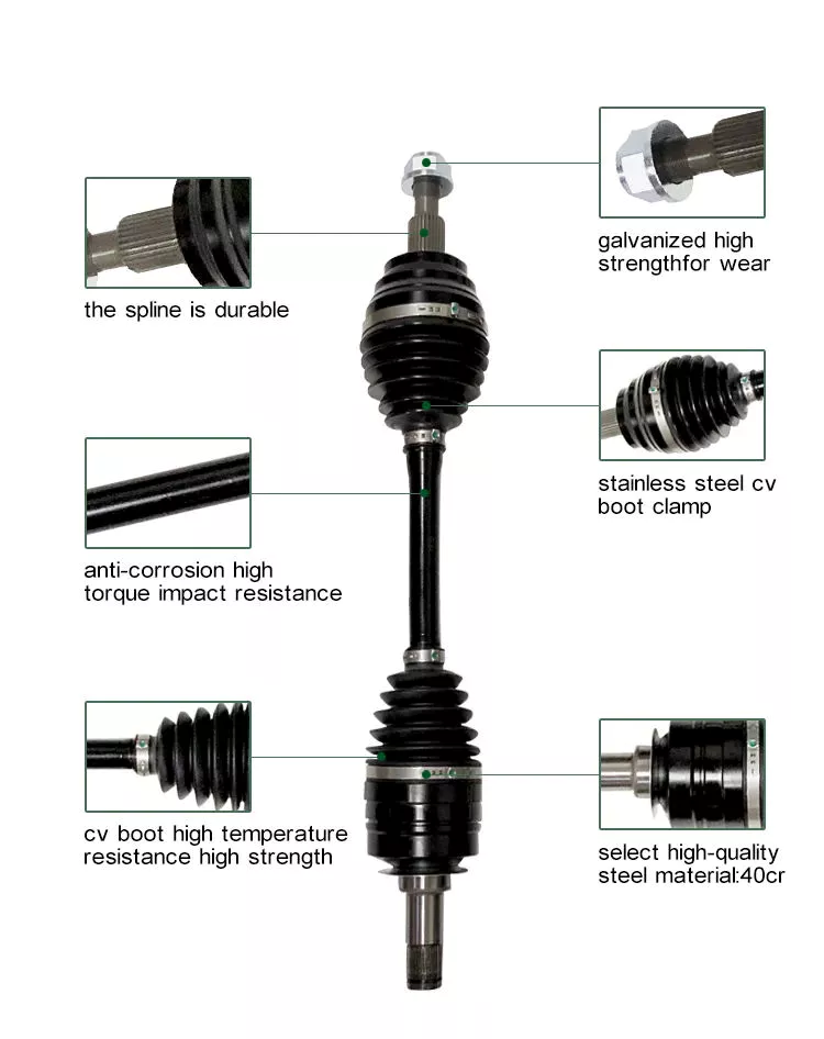
Kunt u de verschillende soorten aandrijfassen en hun specifieke toepassingen toelichten?
Aandrijfassen zijn er in verschillende soorten, elk ontworpen voor specifieke toepassingen en eisen. De keuze van de aandrijfas hangt af van factoren zoals het type voertuig of machine, de benodigde krachtoverbrenging, ruimtebeperkingen en bedrijfsomstandigheden. Hieronder volgt een uitleg van de verschillende soorten aandrijfassen en hun specifieke toepassingen:
1. Massieve as:
Een massieve as, ook wel een eendelige of massief stalen aandrijfas genoemd, is een enkele, ononderbroken as die van de motor of krachtbron naar de aangedreven componenten loopt. Het is een eenvoudig en robuust ontwerp dat in veel toepassingen wordt gebruikt. Massieve assen komen veel voor in voertuigen met achterwielaandrijving, waar ze de kracht van de transmissie naar de achteras overbrengen. Ze worden ook gebruikt in industriële machines, zoals pompen, generatoren en transportbanden, waar een rechte en stijve krachtoverbrenging vereist is.
2. Buisvormige as:
Buisvormige assen, ook wel holle assen genoemd, zijn aandrijfassen met een cilindrische, buisvormige structuur. Ze zijn geconstrueerd met een holle kern en zijn doorgaans lichter dan massieve assen. Buisvormige assen bieden voordelen zoals een lager gewicht, een verbeterde torsiestijfheid en een betere demping van trillingen. Ze worden gebruikt in diverse voertuigen, waaronder auto's, vrachtwagens en motorfietsen, maar ook in industriële apparatuur en machines. Buisvormige aandrijfassen worden veel gebruikt in voertuigen met voorwielaandrijving, waar ze de transmissie met de voorwielen verbinden.
3. Constant Velocity (CV) As:
Homokinetische assen (CV-assen) zijn speciaal ontworpen om hoekbewegingen op te vangen en een constante snelheid te handhaven tussen de motor/transmissie en de aangedreven componenten. Ze zijn voorzien van homokinetische koppelingen aan beide uiteinden, die flexibiliteit en compensatie bieden voor veranderingen in de hoek. Homokinetische assen worden veel gebruikt in voertuigen met voorwielaandrijving en vierwielaandrijving, maar ook in terreinwagens en bepaalde zware machines. De homokinetische koppelingen zorgen voor een soepele krachtoverbrenging, zelfs wanneer de wielen draaien of de ophanging beweegt, waardoor trillingen worden verminderd en de algehele prestaties worden verbeterd.
4. Schuifkoppelingsas:
Schuifassen, ook wel telescopische assen genoemd, bestaan uit twee of meer buisvormige secties die in en uit elkaar kunnen schuiven. Dit ontwerp maakt lengteverstelling mogelijk, waardoor veranderingen in de afstand tussen de motor/transmissie en de aangedreven componenten kunnen worden opgevangen. Schuifassen worden veel gebruikt in voertuigen met een lange wielbasis of verstelbare veersystemen, zoals sommige vrachtwagens, bussen en campers. Door de flexibiliteit in lengte te bieden, zorgen schuifassen voor een constante krachtoverbrenging, zelfs wanneer het chassis van het voertuig beweegt of de geometrie van de ophanging verandert.
5. Dubbele cardanas:
Een dubbele cardanas, ook wel dubbele kruiskoppelingsas genoemd, is een type aandrijfas met twee kruiskoppelingen. Deze configuratie helpt trillingen te verminderen en de werkingshoeken van de koppelingen te minimaliseren, wat resulteert in een soepelere krachtoverbrenging. Dubbele cardanassen worden veel gebruikt in zware toepassingen, zoals vrachtwagens, terreinwagens en landbouwmachines. Ze zijn bijzonder geschikt voor toepassingen met hoge koppelvereisten en grote werkingshoeken, en bieden verbeterde duurzaamheid en prestaties.
6. Samengestelde schacht:
Aandrijfassen van composietmateriaal worden gemaakt van composietmaterialen zoals koolstofvezel of glasvezel, wat voordelen biedt zoals een lager gewicht, verbeterde sterkte en corrosiebestendigheid. Composiet aandrijfassen worden steeds vaker gebruikt in krachtige voertuigen, sportwagens en raceauto's, waar gewichtsvermindering en een verbeterde vermogen-gewichtsverhouding cruciaal zijn. De composietconstructie maakt een nauwkeurige afstemming van de stijfheid en dempingseigenschappen mogelijk, wat resulteert in verbeterde voertuigdynamiek en efficiëntie van de aandrijflijn.
7. Aftakas:
Aftakasassen (PTO-assen) zijn gespecialiseerde aandrijfassen die worden gebruikt in landbouwmachines en bepaalde industriële apparatuur. Ze zijn ontworpen om vermogen over te brengen van de motor of krachtbron naar diverse aanbouwdelen, zoals maaiers, balenpersen of pompen. Aftakasassen hebben doorgaans een spieverbinding aan het ene uiteinde voor de aansluiting op de krachtbron en een kruiskoppeling aan het andere uiteinde voor hoekbewegingen. Ze kenmerken zich door hun vermogen om hoge koppelwaarden over te brengen en hun compatibiliteit met een breed scala aan aangedreven werktuigen.
8. Scheepsas:
Scheepsassen, ook wel schroefassen of staartassen genoemd, zijn speciaal ontworpen voor schepen. Ze brengen de kracht van de motor over op de schroef, waardoor de voortstuwing mogelijk wordt. Scheepsassen zijn meestal lang en werken in een ruwe omgeving, blootgesteld aan water, corrosie en hoge koppelbelastingen. Ze zijn doorgaans gemaakt van roestvrij staal of andere corrosiebestendige materialen en zijn ontworpen om de zware omstandigheden in maritieme toepassingen te weerstaan.
Het is belangrijk om te weten dat de specifieke toepassingen van aandrijfassen kunnen variëren afhankelijk van de fabrikant van het voertuig of de apparatuur, evenals de specifieke ontwerp- en technische eisen. De bovenstaande voorbeelden illustreren gangbare toepassingen voor elk type aandrijfas, maar er kunnen aanvullende varianten en gespecialiseerde ontwerpen bestaan op basis van specifieke branchebehoeften en technologische ontwikkelingen.


editor by CX 2024-04-16