
Produktbeschreibung
CE Certification Agricultural Wide Angle Tractor Factory Supply 6 Spline 540 Pto Drive Shaft for Bush Hog with Yoke Adapter Parts
Produktbeschreibung
PTO drive shaft
Brand New Replacement PTO shaft for Finish Mowers, Tillers, Spreaders, Hay Tedders and many more applications.
PTO is a series 4, rated for 40HP it has 1-3/8″ 6 spline push pin on both ends for easy installment. Complete with safety shield, The PTO measures 43″ from end to end and has an 58″ maximum extended length.
These PTO shafts fit the following Finish Mowers:
Bush Hog: ATH 600 and ATH 720, ATH 900, FTH 480, FTH 600, FTH 720, MTH 600, MTH 720 Series Mowers;
Landpride: FDR1548, FDR1560, FDR1572, FDR1648, FDR1660, FDR1672, FDR2548, FDR2560, FDR2572, AT2660, AT2672 Series Mowers;
Kubota: BL348A, B342A; Caroni TC480, TC590, TC710, TC910 with spline Input Shaft;
Ever-power most late models with splined input shafts, early models had some with smooth input shaft;
1. PTO Drive Shafts
PTO SHAFT WITH QUICK RELEASE YOKES AND OVER-RUNNING CLUTCH(RA), YOU CAN CHOOSE THE LENGTH
Chinabase is a professional manufacturer of PTO SHAFTS for farm machines and agricultural tractors from China. We provide more than 8 sizes of PTO shafts. There is also a full range of safety devices for agricultural applications. Our products are sold to America, Europe and all over the world. We will supply best quality products in most reasonable price.
Following are the tips how to order your PTO shafts:
2. Closed overall length (or cross to cross) of a PTO shaft.
3. Tubes or Pipes
We’ve already got Triangular profile tube and Lemon profile tube for all the series we provide.
And we have some star tube, splined tube and other profile tubes but only for a certain sizes.
4. End yokes
We’ve got 13 types of splined yokes and 8 types of plain bore yokes. I will suggest the usual type for your reference.
You can also send drawings or pictures to us if you cannot find your item in our catalog.
5. Safety devices or clutches
I will attach the details of safety devices for your reference. We’ve already have Free wheel (RA), Ratchet torque limiter(SA),
Shear bolt torque limiter(SB), 3types of friction torque limiter (FF,FFS,FCS) and overrunning couplers(adapters) (FAS).
6. For any other more special requirements with plastic guard, connection method, color of painting, package, etc., please feel free to let me know.
Tube types
| Spline tube | Lemon tube |
| Star tube | Trigonal tube |
|
Function of PTO Shaft |
Antriebswellenteile & Kraftübertragung |
|
Usage of PTO Shaft |
Arten von Traktoren und landwirtschaftlichen Geräten |
|
Yoke Types for PTO Shaft |
Double push pin, Bolt pins, Split pins, Pushpin, Quick release, Ball attachment, Collar….. |
|
Verarbeitung des Jochs |
Schmieden |
|
PTO Shaft Plastic Cover |
YW; BW; YS; BS; Etc |
|
Farben der Zapfwelle |
Green; Orange; Yellow; Black Ect. |
|
Zapfwellenserie |
T1-T10; L1-L6; S6-S10; 10 PS-150 PS mit SA, RA, SB, SFF, WA, CV usw. |
|
Rohrtypen für Zapfwellen |
Lemon, Triangular, Star, Square, Hexangular, Spline, Special Ect |
|
Verarbeitung von Rohren |
Kalt gezogen |
|
Spline Types for PTO Shaft |
1 1/8″ Z6;1 3/8″ Z6; 1 3/8″ Z21 ;1 3/4″ Z20; 1 3/4″ Z6; 8-38*32*6 8-42*36*7; 8-48*42*8; |
Anwendung
Unternehmensprofil
Our factory is a leading manufacturer of PTO shaft yoke and universal joint.
We manufacture high quality PTO yokes for various vehicles, construction machinery and equipment. All products are constructed with rotating lighter.
We are currently exporting our products throughout the world, especially to North America, South America, Europe, and Russia. If you are interested in any item, please do not hesitate to contact us. We are looking CZPT to becoming your suppliers in the near future.
Verpackung & Versand
Zertifizierungen
Related products
You can click the picture to learn about relevant products
Installation Instructions
PTO SHAFT INSTALLATION INSTRUCTION
Install assembly
1 press-fit plastic pipe and plastic cap,
2 fill the groove on the CZPT with oil
3. Slide the nylon bearing into the groove 4. Align nylon bearing and plastic protective cover
Disassembly
1. remove the nylon bearing clamp (three places) with a screwdriver, and then separate the steel pipe and plastic protective cover.
2. Take off the nylon bearing from the groove of the yokes.
3. repeat the above-mentioned steps for the other side.
SHORTENING THE PTO DRIVESHAFT
1. Remove the safety shield.
2. Shorten the inner and outer tubes according to the required length, and the inner and outer tubes shall be shortened by the same length at 1 time
3. Deburr edges of the drive tubes with a file and remove all filings from the tubes.
4. Shorten the inner and outer plastic pipes according to the required length, and the inner and outer plastic pipes shall be
shortened by the same length at 1 time.
5. Grease the internal drive tubes and reassemble them with a safety shield.
Check the minimum and maximum length of the driveshaft installed on the machine. In working condition, the drive tubes should overlap 2/3 length and the plastic tube should never be separated
| Material: | Carbon Steel |
|---|---|
| Load: | Antriebswelle |
| Stiffness & Flexibility: | Flexible Shaft |
| Journal Diameter Dimensional Accuracy: | IT6-IT9 |
| Axis Shape: | Straight Shaft |
| Shaft Shape: | Real Axis |
| Proben: |
US$ 9999/Piece
1 Stück (Mindestbestellmenge) | |
|---|
How do PTO drive shafts handle variations in length and connection methods?
PTO (Power Take-Off) drive shafts are designed to handle variations in length and connection methods, allowing them to be adaptable to different equipment setups and applications. These variations are accommodated through the following features and mechanisms:
1. Telescoping Design:
Many PTO drive shafts are designed with a telescoping mechanism, which enables the length of the drive shaft to be adjusted. Telescoping allows for flexibility in matching the distance between the power source (e.g., tractor PTO) and the driven equipment. By extending or retracting the telescoping sections of the drive shaft, operators can achieve the desired length and ensure proper alignment. This feature is particularly useful when connecting equipment that may have varying distances from the power source.
2. Overlapping Tubes:
PTO drive shafts often consist of multiple tubes that overlap when the drive shaft is fully collapsed. These overlapping tubes provide structural stability and allow for the length adjustment of the drive shaft. By extending or retracting the drive shaft, the overlapping tubes slide within each other, accommodating variations in length. The overlapping tube design ensures that the drive shaft maintains its integrity and alignment during operation.
3. Splined Connections:
PTO drive shafts typically feature splined connections, which provide a secure and reliable method of joining the drive shaft components. Splines are ridges or teeth machined onto the drive shaft and mating component, such as the yoke or flange. The splined connections allow for angular misalignment and axial movement while transmitting power smoothly. They can accommodate variations in length by allowing the drive shaft to extend or retract without compromising the torque transfer capabilities.
4. Locking Mechanisms:
To ensure the stability and safety of the PTO drive shaft, locking mechanisms are incorporated into the design. These mechanisms secure the telescoping sections or splined connections in place once the desired length is achieved. Common locking mechanisms include spring-loaded pins, quick-release collars, or locking rings. These mechanisms prevent unintentional movement or separation of the drive shaft components during operation, ensuring a secure connection even under dynamic loads.
5. Universal Joints:
Universal joints are integral components of PTO drive shafts that allow for angular misalignment between the driving and driven shafts. They consist of two yokes connected by a cross-shaped bearing. Universal joints accommodate variations in length and connection angles, allowing the drive shaft to transfer power smoothly and efficiently even when the equipment is not perfectly aligned. The flexibility of universal joints helps compensate for any misalignment caused by changes in length or connection methods.
6. Adapters and Couplings:
In situations where there are differences in connection methods or sizes between the power source and the driven equipment, adapters and couplings can be used. These components bridge the gap between different connection types, allowing the PTO drive shaft to be compatible with a wider range of equipment. Adapters and couplings may include flanges, spline adapters, or quick-detach couplers, depending on the specific connection requirements.
7. Customization Options:
Manufacturers of PTO drive shafts often provide customization options to accommodate specific length and connection requirements. Customers can request drive shafts of different lengths or specify the types of connections needed for their particular equipment. Customization allows for precise tailoring of the PTO drive shafts to match the equipment setup, ensuring optimal performance and compatibility.
In summary, PTO drive shafts handle variations in length and connection methods through telescoping designs, overlapping tubes, splined connections, locking mechanisms, universal joints, adapters, couplings, and customization options. These features and mechanisms provide the necessary flexibility and adjustability to accommodate different equipment setups and ensure efficient power transfer. Whether it’s adjusting the length, adapting to varying connection types, or compensating for misalignment, PTO drive shafts are designed to handle the variations encountered in different applications and industries.
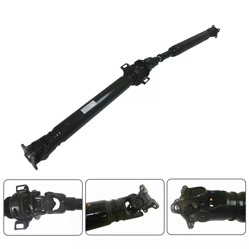
Wie verbessern Zapfwellen die Leistung von Traktoren und Landmaschinen?
Zapfwellen (PTO) spielen eine entscheidende Rolle für die Leistungsfähigkeit von Traktoren und Landmaschinen. Sie gewährleisten eine zuverlässige und effiziente Kraftübertragung, ermöglichen vielfältige Funktionen und steigern die Gesamtproduktivität. So verbessern Zapfwellen die Leistung von Traktoren und Landmaschinen:
1. Vielseitigkeit und Kompatibilität:
Zapfwellen sind vielseitig einsetzbar und mit einer breiten Palette landwirtschaftlicher Geräte und Maschinen kompatibel. Sie sind in standardisierten Größen und Ausführungen erhältlich und ermöglichen so ein einfaches An- und Abkoppeln der Anbaugeräte. Dank dieser Kompatibilität können Landwirte und Maschinenführer schnell zwischen verschiedenen Anbaugeräten wie Pflügen, Mähwerken, Ballenpressen und Sämaschinen wechseln, ohne dass umfangreiche Änderungen oder Modifikationen an der Ausrüstung erforderlich sind. Die Vielseitigkeit der Zapfwellen erhöht die Flexibilität und Effizienz landwirtschaftlicher Maschinen und ermöglicht ihnen die problemlose Ausführung mehrerer Aufgaben.
2. Energieübertragung:
Eine der Hauptfunktionen von Zapfwellen ist die Kraftübertragung vom Traktormotor auf verschiedene landwirtschaftliche Anbaugeräte. Sie übertragen die Rotationskraft mit konstanter Drehzahl und ermöglichen so den effizienten Betrieb der Anbaugeräte. Diese direkte Kraftübertragung macht separate Motoren für jedes Anbaugerät überflüssig und spart dadurch Zeit und Ressourcen. Zapfwellen bieten eine zuverlässige und effiziente Kraftübertragung und gewährleisten so die optimale Leistung landwirtschaftlicher Maschinen.
3. Gesteigerte Produktivität:
Durch den Anschluss verschiedener Anbaugeräte tragen Zapfwellen wesentlich zur Produktivitätssteigerung bei. Traktoren mit Zapfwellen können schnell zwischen verschiedenen Arbeitsgängen wie Pflügen, Säen und Ernten wechseln, ohne dass lange Stillstandszeiten oder Gerätewechsel erforderlich sind. So können Landwirte ihre Maschinen optimal nutzen und Aufgaben termingerecht erledigen. Die Möglichkeit, Anbaugeräte einfach über Zapfwellen anzuschließen und abzukoppeln, steigert die Gesamtproduktivität in der Landwirtschaft.
4. Zeiteffizienz:
Zapfwellenantriebe spielen eine entscheidende Rolle bei der Zeitersparnis in der Landwirtschaft. Sie machen manuelle oder tiergestützte Arbeit überflüssig und ermöglichen so schnellere und effizientere Arbeitsabläufe. Mit Zapfwellenantrieben können Landmaschinen Aufgaben wie Pflügen, Fräsen und Mähen gleichmäßig und effizient erledigen. Diese Zeitersparnis steigert die Gesamtproduktivität des Betriebs und ermöglicht es den Landwirten, größere Flächen in kürzerer Zeit zu bearbeiten.
5. Präzise Leistungssteuerung:
Zapfwellenantriebe ermöglichen eine präzise Leistungssteuerung und erlauben es dem Bediener, die Drehzahl der Anbaugeräte an die jeweiligen Arbeitsanforderungen anzupassen. Diese Steuerung ist besonders wertvoll bei Aufgaben wie Mähen oder Spritzen, da unterschiedliche Vegetations- oder Pflanzenarten spezifische Leistungseinstellungen erfordern. Mit Zapfwellenantrieben können Bediener die Leistungsabgabe feinabstimmen, um optimale Ergebnisse zu erzielen und so einen effizienten und effektiven Betrieb der Landmaschinen zu gewährleisten.
6. Reduzierte Ermüdung des Bedieners:
Der Einsatz von Zapfwellenantrieben reduziert die körperliche Belastung der Bediener. Anstatt manuelle Kraft oder Tierkraft zum Betrieb von Anbaugeräten zu benötigen, können die Bediener die über die Zapfwelle übertragene Kraft nutzen. Dies verringert die Ermüdung und ermöglicht es den Bedienern, länger ohne übermäßige Erschöpfung zu arbeiten. Die geringere Ermüdung der Bediener trägt zu einer höheren Produktivität und Gesamtleistung bei landwirtschaftlichen Arbeiten bei.
7. Integration mit moderner Technologie:
Zapfwellenantriebe lassen sich in moderne Traktortechnik und Steuerungssysteme integrieren. Diese Integration ermöglicht die komfortable und präzise Steuerung des Zapfwellenein- und -ausschaltvorgangs, der Drehzahl und weiterer Parameter. Traktoren mit Zapfwellenantrieb können mit GPS-Lenksystemen, Präzisionslandwirtschaftstechnologien und Datenmanagementsystemen kombiniert werden, wodurch Leistung und Effizienz in der Landwirtschaft weiter gesteigert werden.
8. Wartungsfreundlichkeit:
Zapfwellenantriebe sind in der Regel wartungsfreundlich konstruiert. Sie verfügen oft über leicht zugängliche Schmierstellen, Inspektionsöffnungen und austauschbare Komponenten, was die Instandhaltung erleichtert. Regelmäßige Wartung gewährleistet optimale Leistung, reduziert das Risiko unerwarteter Ausfälle und maximiert die Effizienz von Traktoren und Landmaschinen.
Zusammenfassend lässt sich sagen, dass Zapfwellen die Leistung von Traktoren und Landmaschinen durch ihre Vielseitigkeit, die Kraftübertragung, die Steigerung der Produktivität, die Zeitersparnis, die präzise Leistungssteuerung, die Reduzierung der Fahrerermüdung, die Integration mit moderner Technologie und die erleichterte Wartung verbessern. Dank der Möglichkeiten von Zapfwellen können Landwirte und Maschinenführer ihre Maschinen effizient und effektiv betreiben, was letztendlich zu einer höheren Produktivität und Rentabilität in der Landwirtschaft führt.
Can you explain the components and function of a PTO drive shaft system?
A PTO (Power Take-Off) drive shaft system consists of several components that work together to transfer power from a primary power source, such as a tractor or engine, to various implements or machinery. Each component plays a specific role in ensuring the efficient and reliable transmission of rotational power. Here’s a detailed explanation of the components and their functions within a PTO drive shaft system:
1. Primary Power Source:
The primary power source is typically a tractor or engine equipped with a PTO output shaft. This shaft generates rotational power from the engine’s crankshaft or transmission, acting as the starting point for power transmission.
2. PTO Output Shaft:
The PTO output shaft is a rotating shaft located on the primary power source, specifically designed to transfer power to external devices. It is typically located at the rear of a tractor and may have various spline configurations to accommodate different types of PTO drive shafts.
3. PTO Drive Shaft:
The PTO drive shaft is the main component of the system, responsible for transmitting power from the primary power source to the implement or machinery. It consists of a rotating shaft with splines at both ends. One end connects to the PTO output shaft, while the other end connects to the input shaft of the implement. The drive shaft rotates at the same speed as the primary power source, effectively delivering power to the implement.
4. Splined Connections:
The splined connections on the PTO drive shaft and the PTO output shaft of the primary power source provide a secure and robust connection. These splines ensure proper alignment and torque transmission between the two shafts, enabling efficient power transfer while accommodating varying distances and alignments.
5. Safety Guards and Shields:
PTO drive shaft systems often incorporate safety guards and shields to protect operators from potential hazards associated with rotating components. These guards and shields cover the rotating parts of the drive shaft, reducing the risk of entanglement or contact during operation.
6. Telescoping or Sliding Mechanism:
Some PTO drive shafts feature a telescoping or sliding mechanism. This allows the drive shaft to be adjusted in length, accommodating different distances between the primary power source and the implement. The telescoping or sliding mechanism ensures proper alignment and prevents excessive tension or binding of the drive shaft.
7. Shear Pins or Clutch Mechanism:
To protect the PTO drive shaft and the machinery from excessive loads or sudden shocks, shear pins or a clutch mechanism may be incorporated. These safety features are designed to disconnect the drive shaft from the primary power source in the event of an overload or sudden impact, preventing damage to the drive shaft and associated equipment.
8. Maintenance and Lubrication Points:
PTO drive shaft systems require regular maintenance and lubrication to ensure optimal performance and longevity. Lubrication points are typically provided to allow for the application of grease or oil to reduce friction and wear. Regular inspections and maintenance help identify any issues or wear in the components, ensuring safe and efficient operation.
9. Implement Input Shaft:
The implement input shaft is the counterpart to the PTO drive shaft on the implement or machinery side. It connects to the PTO drive shaft and receives power for driving the specific machinery or performing various tasks. The input shaft is precisely aligned with the drive shaft to ensure efficient power transfer.
In summary, a PTO drive shaft system consists of components such as the primary power source, PTO output shaft, PTO drive shaft, splined connections, safety guards, telescoping or sliding mechanisms, shear pins or clutch mechanisms, maintenance and lubrication points, and the implement input shaft. Together, these components enable the efficient and reliable transfer of rotational power from the primary power source to the implement or machinery, allowing for a wide range of tasks and applications in agricultural and industrial settings.


Bearbeitet von CX am 06.11.2023