 Getting the PTO shaft length wrong is not a minor inconvenience. On an underpowered baler working the fenlands of Lincolnshire or a hydraulic pump driving a spreader across the Yorkshire Wolds, an incorrectly sized power take-off drive shaft can destroy universal joints within hours, buckle telescoping tubes under compression, or at worst create a catastrophic mechanical separation that puts operators in genuine danger. Despite this, shaft length remains one of the most frequently miscalculated parameters when sourcing PTO drive shafts, largely because the measurement process involves variables that interact in non-obvious ways: operating angle, implement offset, tractor drawbar geometry, and the compression-to-extension ratio of the sliding yoke assembly.
This guide draws on decades of mechanical power transmission engineering practice to walk you through every dimension you need to consider, from the physical tape-measure steps to the engineering tolerances that separate a reliable shaft from a hazardous one. Whether you are sourcing for a single machine in a West Midlands workshop or specifying a fleet of shafts for a Sheffield-based contract hire operation, the principles remain the same, and the accuracy standards are non-negotiable.
⚡ Get a Quote — [email protected]
Fast response · UK-focused · Custom shaft specifications welcome
Why Shaft Length Is the Critical Variable Nobody Talks About
Too Short: Mechanical Separation Risk
When a PTO shaft is too short, the sliding yoke reaches the end of its travel at full extension, commonly when the implement turns sharply or the tractor crests a rise. At that moment, the shaft pulls apart under load. This is not a gradual failure; it is instantaneous and violent. The separated shaft becomes a projectile or drops onto the ground, potentially catching a rotating component and creating a secondary hazard. In UK field operations where bystanders and farm workers may be working within the machine’s turning circle, a separation event is a serious safety incident that must be prevented by correct specification from the outset.
Too Long: Tube Bottoming and Bearing Overload
Excess length causes the outer tube to bottom out against the inner tube when the implement is close-coupled to the tractor. This locks the sliding function, turning the telescoping tube into a rigid bar and transferring all relative movement through the universal joints at extreme angles. Over-stressing the crosses and bearings in this way produces rapid wear, vibration, and eventual joint failure, typically within one or two seasons of heavy use. The characteristic symptom is a rhythmic knocking or vibration that gets progressively worse over weeks, often wrongly diagnosed as gearbox trouble before the shaft is identified as the root cause.
The Operating Angle Effect on Apparent Length
Many operators measure their PTO drive shaft with the machine in a straight-line configuration and order a replacement based on that single measurement. What they miss is that as the tractor pivots, whether turning in a headland or climbing out of a low gateway, the geometrical relationship between the tractor PTO stub and the implement input shaft changes. The shaft must shorten when the connection point diverges laterally, and that shortening must be absorbed by the sliding section without bottoming out. On a mid-size UK tractor with a 70-degree maximum articulation, this apparent length change can exceed 120 mm from straight to full-lock.
The Step-by-Step Measurement Process
Follow every stage without shortcuts. Each step adds a non-trivial constraint on the final shaft specification.
Position the Implement Correctly
Attach the implement to the tractor in its normal working position, three-point linkage at operating height, or drawbar at standard working extension. Do not measure with the linkage at full lift or full drop unless that is genuinely the only operating position. Carry out all measurements on a flat, level surface so that gravity does not introduce a spurious angular offset between tractor and implement. If your farm ground is characteristically uneven, note the maximum slope angle and factor this into your angle calculation.
Measure the Connection-Point Distance
Record the distance between the tractor PTO output stub centre and the implement gearbox input stub centre, measured along the axis of the shaft rather than in a straight line through the air if the two stubs are not co-linear. This is your baseline connected length. Use a rigid straight edge and plumb line if the two shafts are offset vertically or laterally. A common mistake is measuring the linear distance between the two stub faces and adding a fixed offset for the yoke engagement depth; this method introduces errors of 20 mm or more.
Calculate Maximum Extension
Determine the maximum separation that will occur during operation, typically when the tractor is at full steering lock or maximum articulation. For a tractor with a 60-degree maximum steering angle and a 900 mm drawbar length, this adds approximately 150 to 200 mm to the baseline measurement. For three-point linkage work on hilly ground, also consider the maximum lift height and any rearward geometry change it introduces. Take this measurement physically by moving the tractor to full lock and re-measuring.
Apply the Compression Safety Margin
The shaft must never bottom out under any operating condition. Industry practice for agricultural PTO drive shafts requires a minimum of 75 mm of remaining overlap in the sliding section at the point of maximum shaft extension, and the sliding section must never be more than 60% compressed at minimum extension. These two constraints define your permissible shaft-length window. Any shaft specification that does not satisfy both simultaneously is an incorrect specification, regardless of what a catalogue chart may suggest.
Record Yoke Bore and Spline Specification
The physical length means nothing if the yoke geometry is wrong. Confirm the tractor PTO spline count and pitch diameter (commonly 6-spline 1 3/8 inch, or 21-spline 1 3/8 inch, or 20-spline 1 3/4 inch) and the implement input configuration. Note whether the implement uses a shear bolt hub, slip clutch, or free-wheeling device, all of which affect the overall assembly length and must be factored into your measurement. Spline verification is best done with a dedicated gauge rather than by eye.
Verify Against Collapsed and Extended Lengths
A PTO drive shaft’s usable range is defined by two figures: collapsed length and maximum extended length. Your baseline measurement must sit comfortably between these, ideally near the mid-point of the sliding range during straight-line work. If your required connected length is within 60 mm of either extreme, you need a shaft with a larger telescoping range or a customised assembly. Trying to stretch a standard catalogue shaft to an application it does not fit is one of the most common and costly mistakes in shaft procurement.
The 75 / 60 Rule: Your Length Safety Window
The golden rule for PTO drive shaft sizing: at maximum extension, retain at least 75 mm of tube overlap. At minimum extension, the tubes must not compress past 60% of the sliding section’s total travel. Operating outside this window voids manufacturer warranties and creates a measurable risk of component failure that no maintenance schedule can offset.
PTO Shaft Series: Technical Performance Parameters
Standard specifications across the Ever Power PTO drive shaft range. Custom configurations available on request.
| Loạt | Max. Torque | Max. Angle | Vật liệu ống | Hồ sơ Spline | Collapsed L. | Extended L. | RPM | Protection | Typical Use |
|---|---|---|---|---|---|---|---|---|---|
| S1 | 210 Nm | 25 deg | Cold-drawn steel | 6-spline 1 3/8 in | 480-760 mm | 760-1200 mm | 540 | Bu lông cắt | Light rotary tools, small balers |
| S2 | 460 Nm | 25 deg | Cold-drawn steel | 6-spline 1 3/8 in | 540-900 mm | 900-1450 mm | 540 | Slip clutch | Medium balers, mowers |
| S3 | 810 Nm | 25 deg | Alloy steel | 21-spline 1 3/8 in | 600-980 mm | 980-1600 mm | 1000 | Slip + FW | Large balers, telehandlers |
| S4 | 1340 Nm | 25 deg | Alloy steel | 20-spline 1 3/4 in | 680-1100 mm | 1100-1800 mm | 1000 | Torque limiter | Combines, heavy slurry tankers |
| S5 | 2400 Nm | 25 deg | High-strength alloy | 20-spline 1 3/4 in | 760-1220 mm | 1220-2000 mm | 1000 | Ratchet + FW | Industrial pumps, generators |
| S6 HD | 3800 Nm | 25 deg | 4140 Chromoly | Custom / flange | Phong tục | Phong tục | 1000 | Full custom | Mining, offshore, heavy plant |
FW = Free-wheeling device. Torque ratings at continuous operating load. Intermittent peak capacity typically 2.5x continuous. Contact Ever Power for custom specifications.
Correct safety-guard coverage is a legal requirement under UK PUWER 1998 for all rotating PTO shaft assemblies.
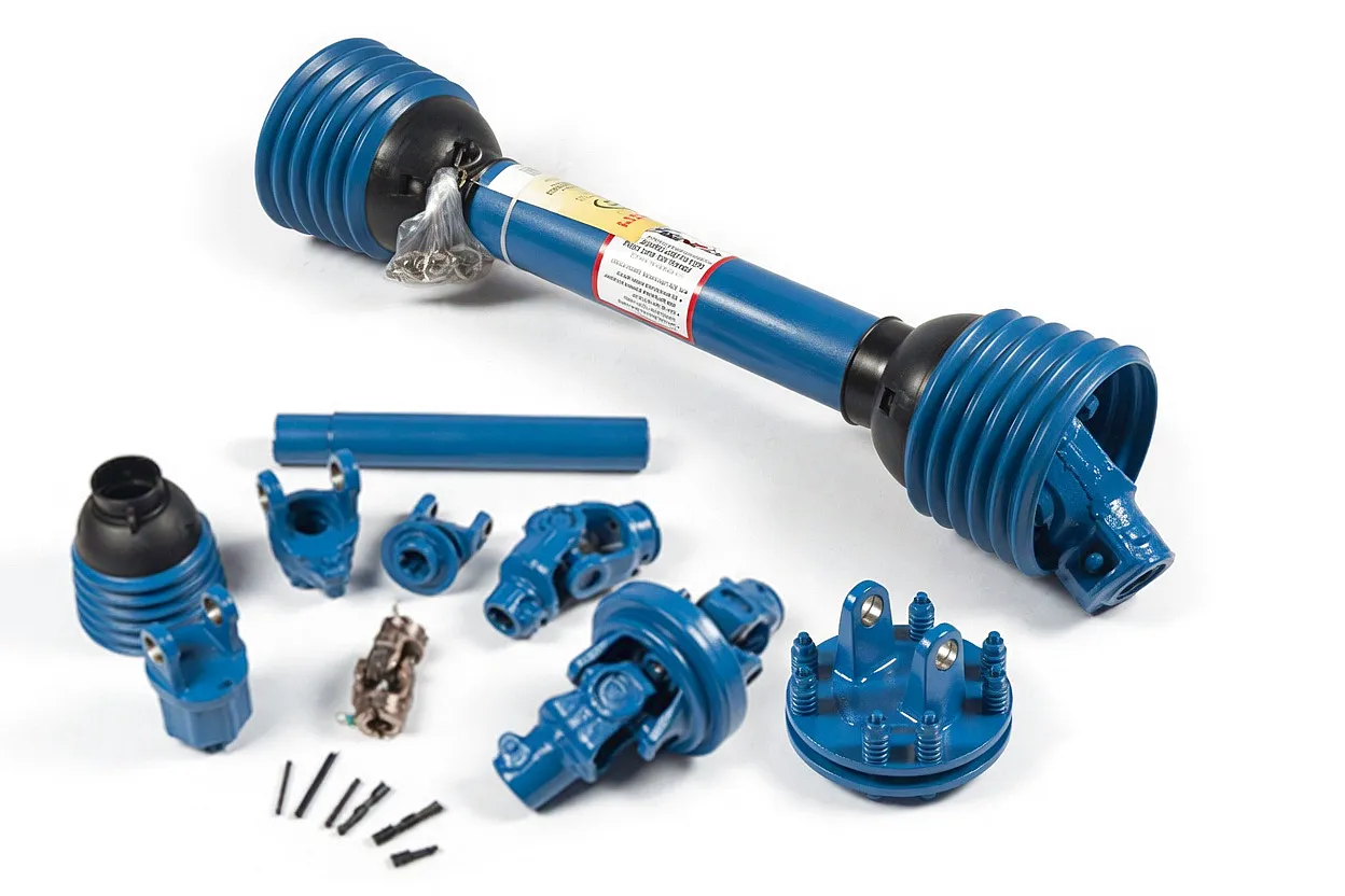
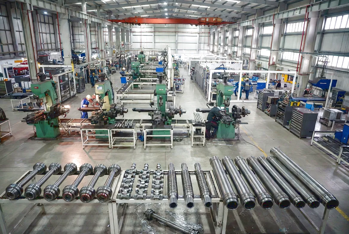
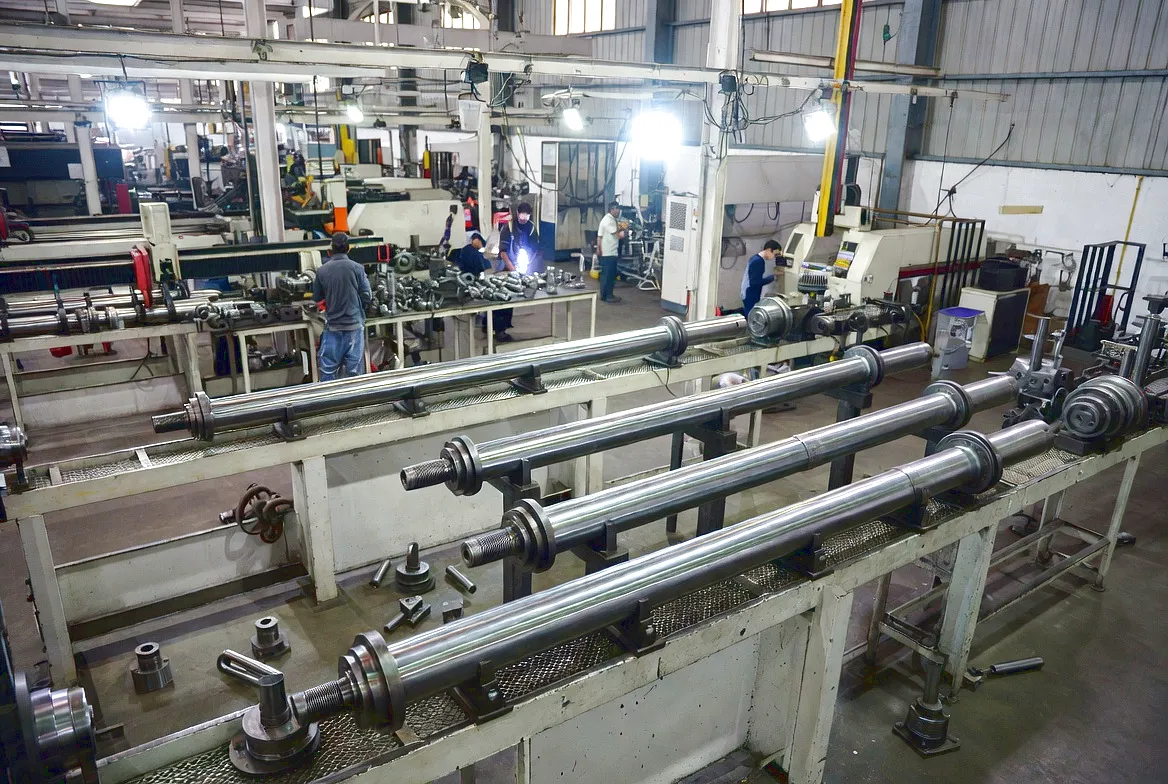
How a PTO Shaft Actually Works: The Engineering Inside
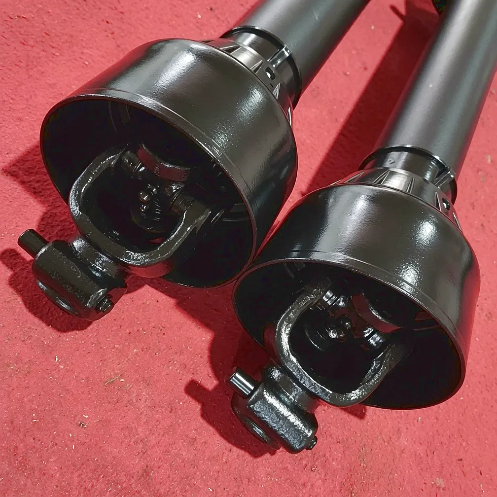
A power take-off drive shaft is deceptively simple in appearance, a rotating tube with fittings at each end, but the engineering that makes it work reliably at 540 or 1,000 RPM under kilonewton-metre torque loads across a variable angular misalignment is genuinely sophisticated. At the heart of every shaft are the universal joints, typically of the Hooke’s-joint type, which allow rotational power to be transmitted across an angular offset. A single universal joint produces a velocity variation: the output shaft accelerates and decelerates twice per revolution at any operating angle. This variation increases with the angle of operation, and at 25 degrees it becomes significant enough to induce vibration that fatigues bearings, welds, and tube sections over thousands of operating hours.
Double Cardan Constant-Velocity Joints
The velocity variation of a single Hooke’s joint is cancelled by adding a second joint phased 90 degrees relative to the yoke orientation. This double-Cardan arrangement delivers near-constant-velocity output regardless of operating angle, dramatically reducing vibration and extending the service life of both the shaft and the implement gearbox. It is standard on PTO drive shafts where the operating angle regularly exceeds 15 degrees or where the driven machine is particularly sensitive to speed fluctuations, such as precision seeders and high-speed cutterbar mowers.
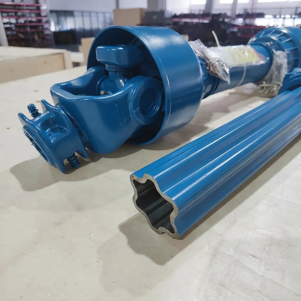
The Telescoping Sliding Section
The sliding profile, typically a star-shaped or lemon-shaped cross-section machined into both inner and outer tube, serves two purposes simultaneously. It transmits torque through the profile engagement while allowing the assembly to extend and contract freely along its axis as the distance between tractor and implement changes. Profile surfaces are precision-machined and fitted with grease-compatible polymer bushings to minimise wear and reduce sliding effort during operation. The accuracy of the profile geometry directly governs how smoothly the shaft accommodates length changes without binding or backlash.
Overload Protection Devices
Modern PTO drive shafts incorporate an overload protection device designed to disengage before applied torque exceeds the safe limit of the shaft or driven implement. Options include shear bolt hubs, slip clutches, ratchet clutches, and friction torque limiters. Selecting the correct protection device for your application is as important as selecting the correct shaft length, because an undersized slip clutch will chatter during normal operation while an oversized one will fail to protect at the critical moment. Torque limiters must be set between the continuous operating torque and the structural capacity of the weakest driveline component.
The materials used in PTO drive shaft manufacture directly govern weight, torsional stiffness, and fatigue resistance. Tubes are most commonly produced from cold-drawn seamless steel, either SAE 1020 carbon steel for standard series or 4140 chromoly for high-torque industrial applications. Yoke forgings are typically SAE 1045 medium-carbon steel, induction-hardened at the bearing journal surfaces to 58 to 62 HRC while retaining a tough, impact-resistant core. Cross and bearing kits use 52100 bearing steel for the needle bearing elements. This specific combination of hardened surfaces and ductile cores resists both rolling-contact fatigue and the shock-load events that occur during implement engagement and ground strikes.
Where PTO Shafts Are Specified Across UK Industry
From the arable heartlands of East Anglia to the engineering workshops of the West Midlands, correct PTO shaft sizing underpins productive operation across every sector.
Precision-Built. Infinitely Configurable. UK-Ready.
Ever Power operates a comprehensively equipped PTO drive shaft manufacturing facility producing shafts that serve clients across the UK, continental Europe, and global export markets. The facility runs a dedicated custom engineering division specifically configured for non-standard specifications, because the reality of UK agriculture and industry is that no two applications are identical. When a Shropshire mixed-farm business needs a shaft connecting a John Deere 6155R to a bespoke slurry injector built by a local workshop, or when a Sheffield industrial equipment manufacturer needs five hundred hydraulic pump drive shafts to a tight dimensional specification, Ever Power’s engineering team produces full technical drawings for client approval before a single component is manufactured.
The manufacturing process begins with CNC tube cutting and end forming, proceeds through precision-machined yoke forgings, and concludes with robotic welding, heat treatment, and CMM-verified quality inspection. Every shaft is proof-tested at 120% of its rated torque before despatch, and traceability documentation including batch numbers, material certifications, and inspection records is supplied with every commercial order. Delivery to UK freight terminals typically runs on a 14 to 21 day lead time for standard series, with express production available for urgent requirements. Ever Power’s UK-dedicated logistics channel ensures clearance documentation is complete and goods arrive ready for immediate collection or onward delivery.
Ready to Specify Your Custom Shaft?
Send your measurements, connected length, maximum extension, spline type, torque requirement, and application details. The Ever Power technical team returns a full specification and competitive quote within one working day.
Core Technical Advantages of the Ever Power Range
Engineering decisions that separate a quality shaft from a cheap substitute, and why they matter in UK field conditions.
Induction-Hardened Journal Surfaces
Yoke bearing journals are induction-hardened to 58 to 62 HRC at the surface while maintaining a ductile core. This eliminates premature bearing-race wear, the most common cause of U-joint failure in high-cycle applications, extending service intervals by a factor of two to three compared with through-hardened yokes. The dual-layer metallurgy is confirmed by hardness testing on a sample from each production batch.
Polymer-Bushed Sliding Profiles
Profile tubes are lined with UHMW-PE polymer bushings that reduce sliding friction, eliminate metal-to-metal contact, and provide a self-lubricating surface that performs acceptably even when the telescoping section is not re-greased on schedule. This is an important practical advantage in UK agricultural and site operations where maintenance is inevitably deferred during busy seasonal periods.
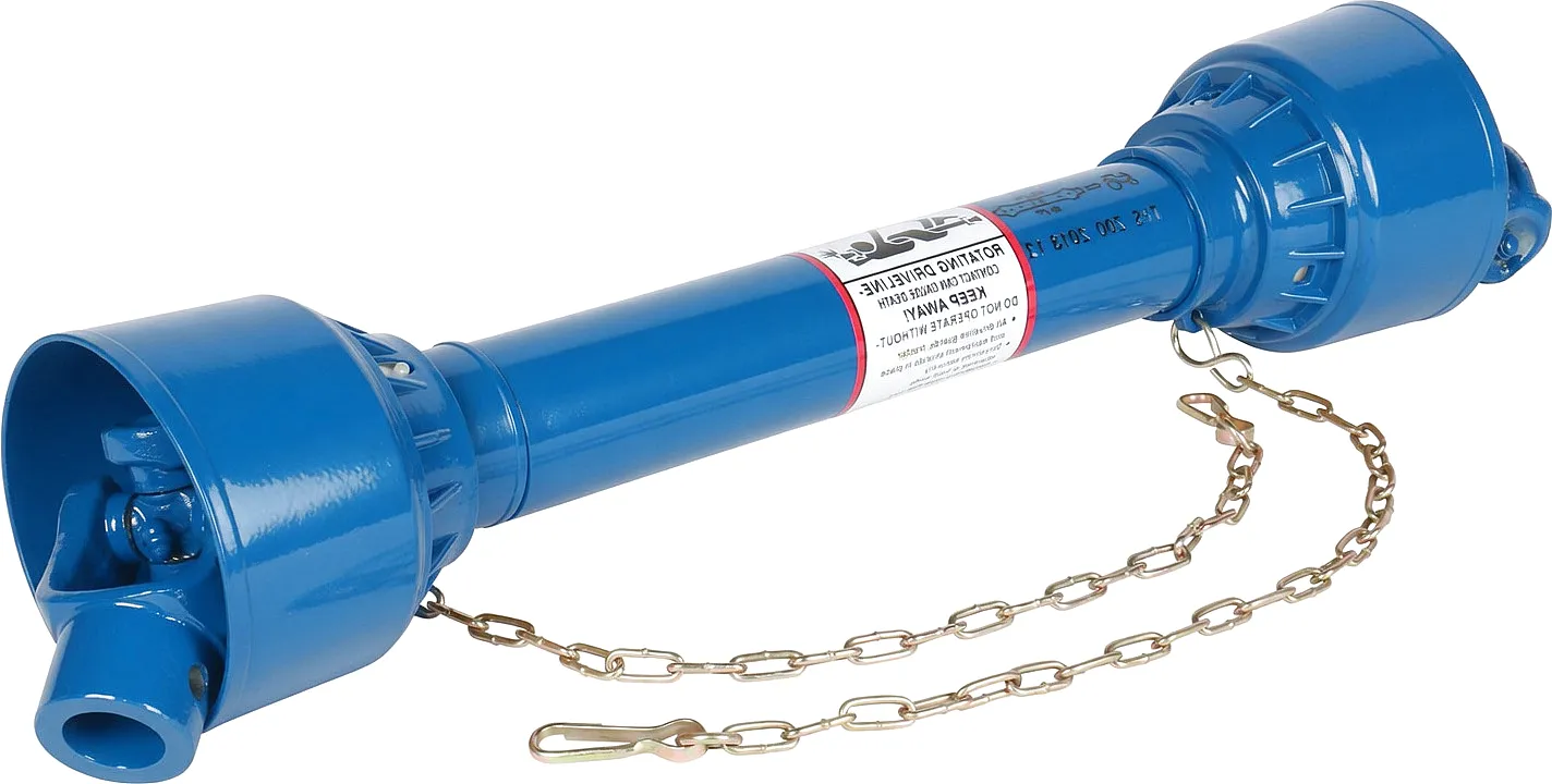
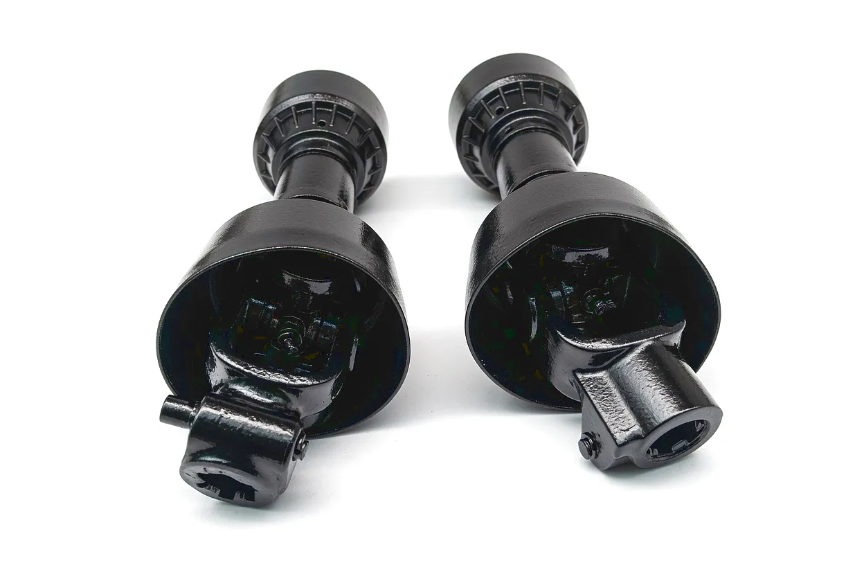
Full-Profile Safety Guard Systems
UK PUWER 1998 regulations require that all rotating PTO shaft assemblies are fully guarded. Ever Power supplies CE-marked guard assemblies positively fixed at both the tractor and implement ends, extending throughout the full shaft travel, and designed to be removed and replaced in under three minutes for maintenance access. Guard retention uses captive spring clips rather than loose ties that can detach and leave rotating shaft exposed.
Calibrated Overload Protection
Every overload protection device is factory-calibrated and supplied with a calibration certificate. The trip torque is set to the value specified at order, typically 1.8 to 2.2 times the continuous operating torque, and the calibration can be re-verified in the field with the supplied test procedure. This eliminates the guesswork that leads to either nuisance tripping or total failure to protect at the critical moment.
Corrosion-Resistant Finish Options
Standard shafts receive a phosphate and oil treatment for indoor storage and seasonal outdoor use. UK operators working in coastal regions such as the Fens, the Somerset Levels, or Scottish lowland farming near the Moray Firth can specify hot-dip galvanised tube and stainless fasteners as an uprated corrosion package, extending shaft service life in high-humidity and high-salt environments by several additional seasons.
CMM-Verified Length Accuracy
Custom-length shafts are measured on a co-ordinate measuring machine at the final inspection stage, with collapsed and extended lengths recorded against the order specification. Where tolerance is plus or minus 1 mm, every shaft either passes or is reworked before despatch. The inspection report is emailed as part of the despatch notification, allowing dimensions to be verified before fitting and avoiding costly downtime from sizing errors discovered at installation.
Real-World Impact
Customer Success Story
How a South Yorkshire operator eliminated recurring PTO shaft failures by addressing a single measurement oversight
What UK Operators Say
“We had been chasing our tails with the same PTO shaft failure for over a year. Ever Power’s team asked questions no supplier had asked before — exactly where the chassis flexes, what the operating angle is at full droop, what material the yokes were on the gearbox side. The shafts they supplied have been on the vehicles for eleven months without a single issue. The measurement checklist they sent over is now standard in our workshop procedure.”
“The double-Cardan shaft Ever Power supplied for our crushing rig has been running for eight months straight, seven days a week during the busy season. We had tried two other suppliers and neither could get the geometry right for the angle we’re operating at. Ever Power asked for the full installation drawing and came back with a specification that worked from day one. Lead time was competitive and the CMM report gave our maintenance engineer confidence before the shaft even went on the machine.”
“Our arable operation runs over 2,000 hectares across Lincolnshire and the shaft lengths we need are rarely off-the-shelf sizes. Ever Power have supplied us with custom-length units for three different tractors and two trailed implements, and every single shaft has been exactly what we ordered. The zinc-phosphate finish they offered holds up well to the washing regime we use post-harvest. Response from their sales team is quick — I’ve had a quote back within two hours of sending dimensions, which matters when we’re trying to keep the combine moving.”
Voice-Search Ready
Frequently Asked Questions
Real questions from UK engineers and fleet managers — answered plainly
chỉnh sửa bởi gzl


