The Fundamental Challenge: Fluid & Chemical Machinery Context
The fluid and chemical industry is characterized by continuous flow processes, where downtime can result in significant economic losses. The primary mechanical requirement in this field is the transmission of torque between the prime mover (electric motor, diesel engine) and the driven machinery (pumps, fans, compressors), which are typically physically separated.
This separation is not arbitrary but rather stems from considerations of process design, safe operating areas, and ease of maintenance. However, this also presents two major threats to the lifespan of the machinery:
- Misalignment: The inability to maintain perfect coaxial alignment between the driver and driven shafts due to installation tolerances, base settling, or thermal growth.
- Vibration Transmission: The propagation of mechanical noise and fluid pulsation through the driveline, potentially leading to resonance and fatigue.
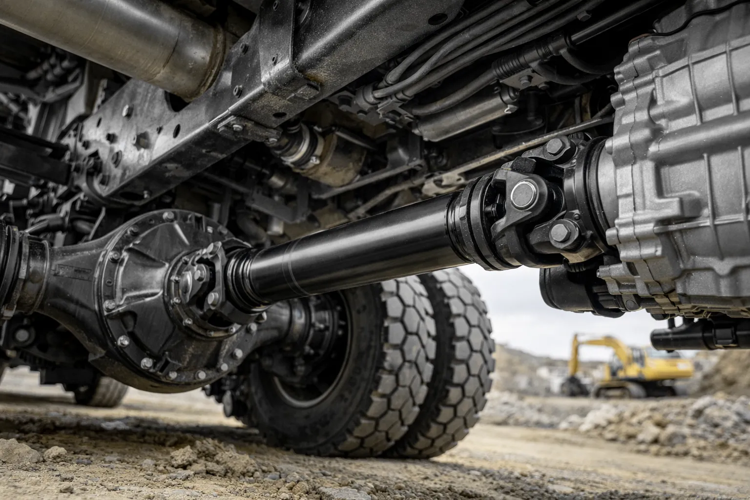
To address these, the universal joint shaft (Cardan shaft) becomes an indispensable component, acting as a flexible link that accommodates movement while transmitting power.
Deep Dive: Industrial Pump Drives
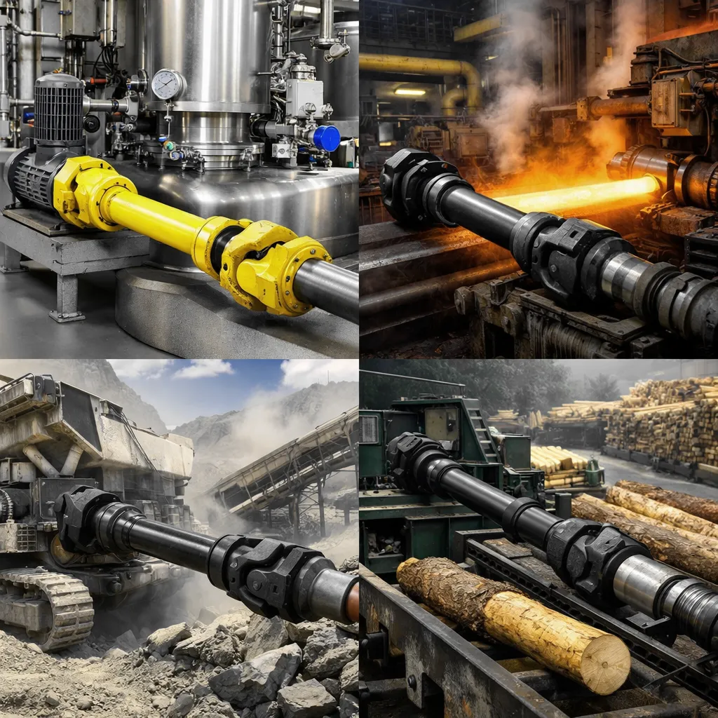
Equipment Definition: This category encompasses a broad spectrum of heavy-duty pumping equipment, including centrifugal pumps, reciprocating plunger pumps, and large-scale sewage pumps. In these configurations, the electric motor is typically coupled to the pump shaft via a universal drive shaft to allow for non-aligned installation and to act as a buffer for shock loads.
The Battle Against Misalignment (Static & Thermal)
The Engineering Problem: In many chemical plants, pumps and motors are mounted on separate skids or foundations. Even with precision laser alignment during installation, “perfect” alignment is a transient state.
Thermal Growth: When a pump delivers a high-temperature fluid (from heat transfer oil to superheated condensate), the pump casing expands, causing the shaft centerline to rise. The motor, however, expands differently in the vertical direction due to its lower operating temperature or varying heating rate. This difference in thermal expansion can cause significant parallel misalignment during operation. If a rigid coupling is used, this will generate enormous radial loads on the mechanical seal and bearings, leading to premature failure.
วิธีแก้ปัญหา: Our high-performance universal shafts are designed to operate at articulation angles that easily accommodate these shifts. By allowing the central intermediate shaft to “float” between the two universal joints, the system effectively neutralises the reaction forces caused by thermal growth, protecting the sensitive pump seals.
Taming the Pulse: Torque Ripple & Reciprocating Pumps
The Phenomenon: Reciprocating piston pumps are notorious for their uneven torque demand. The periodic variations in the suction and discharge strokes create a fluctuating load profile known as torque pulsation.
If the natural frequency of the drive shaft system coincides with the frequency of these pulsations (or their harmonics), the system enters a state of resonance. This can lead to catastrophic failures, such as physical shearing of the shaft or vibration damage to the connected gearbox.
Configuration Strategy: Damping and Flexibility
To combat torsional vibration, UK pto-drive-shafts.com Co.,Ltd. recommends a multi-layered approach:
- Series Configuration with Highly Flexible Couplings: We advocate installing a highly flexible rubber or silicone coupling in series with the universal shaft. The low torsional stiffness of the elastic element shifts the system’s natural frequency below the operating speed range (tuning), while the material’s hysteresis provides damping to dissipate vibration energy.
- Carbon Fibre Composite Shafts: For high-speed or highly dynamic applications, we utilise carbon fibre tubes instead of steel. Carbon fibre composites possess superior internal damping characteristics compared to metals (verified by industry research from gwbdriveshaft.com and geislinger.com). This internal friction helps attenuate high-frequency noise and vibration transmission.
- Low Inertia: The reduced mass of carbon fibre significantly lowers the polar moment of inertia. In systems with rapid load fluctuations, a lower inertia shaft reduces the peak stresses on driveline components during acceleration and deceleration phases.
Material Engineering: Surviving Corrosive Media
The Environment: Chemical machinery often operates in atmospheres laden with acid vapours, alkaline mists, or salt spray. A standard carbon steel cardan shaft, if left unprotected, will suffer from rapid corrosion, pitting, and eventual stress-corrosion cracking.
Our Material Standards:
- Stainless Steel Construction: For the most aggressive environments (e.g., acid transport), we manufacture yokes and tubes from AISI 316L (EN 1.4404) or Duplex Stainless Steel. These grades offer exceptional resistance to chloride pitting and crevice corrosion.
- Advanced Coatings: For larger shafts where solid stainless steel is cost-prohibitive, we employ a multi-barrier defence system. This includes a base layer of Nickel plating or thermal spray zinc, followed by high-build epoxy or polyurethane marine-grade topcoats.
- Sealing Integrity: The Achilles’ heel of any universal joint in a chemical plant is the bearing seal. We utilise double-lip seals made from Viton (FKM), which remains stable in high temperatures and resists degradation from aggressive chemical solvents, ensuring the lubricant stays in and contaminants stay out.
Deep Dive: Cooling Tower Fan Drives
Equipment Definition: Cooling towers are critical heat rejection devices. The standard design involves a large axial fan mounted at the top of the tower (the “stack”), driven by a motor located safely at the base of the tower structure. Connecting these two is a drive shaft that must span a considerable vertical or diagonal distance, often passing through the tower’s interior.
The Long Span Dilemma: Critical Speed Physics
The challenge: Cooling tower drive shafts are typically 3 to 6 meters long (sometimes even exceeding 10 meters). In rotor dynamics, each shaft has a critical speed—the speed at which the shaft’s natural bending frequency matches its rotational frequency, resulting in severe whiplash.
For steel shafts, stiffness decreases and mass increases with length. This causes a sharp drop in critical speed. Typically, for longer steel shafts, the critical speed is lower than the operating speed required by the fan. This physical limitation forces engineers to install intermediate bearings to support the shaft. However, these bearings are located inside the damp and inaccessible cooling tower, making maintenance a nightmare and leading to frequent failures.
The Carbon Fibre Revolution
UK pto-drive-shafts.com Co.,Ltd. champions the use of Composite Fibre Drive Shafts to solve this problem definitively.
- High Specific Modulus: Carbon fibre composites have an exceptional stiffness-to-weight ratio. A carbon shaft is significantly lighter than a steel equivalent but maintains high stiffness. This physical property pushes the critical speed of the shaft upwards, well beyond the operating range of the fan.
- Elimination of Intermediate Bearings: Because the critical speed is higher, we can span much longer distances (up to 6 meters or more) in a single jump without needing centre supports. This “Floating Shaft” design removes the most common point of failure in cooling towers, drastically reducing maintenance costs (TCO).
Comparative Analysis: Steel vs. Carbon Fibre in Cooling Towers
| คุณสมบัติ | Traditional Steel Shaft | Composite (Carbon) Shaft |
|---|---|---|
| น้ำหนัก | Heavy (High load on bearings) | Ultra-light (Reduced load) |
| ความเร็ววิกฤต | Low (Limits span length) | High (Allows long spans) |
| Support | Often requires intermediate bearing | Single span (No center bearing) |
| Corrosion | Susceptible to rust/pitting | Naturally inert & corrosion-free |
| Vibration | Transmits vibration | Dampens vibration |
Reliability in the “Steam Sauna”
The Environment: The interior of a cooling tower is essentially a perpetual saturation zone. It is hot (40°C – 60°C), 100% humid, and the air is often filled with drift water containing biological control chemicals (chlorine, bromine) and dissolved solids. This is a torture chamber for metals.
Technical Response:Our composite shaft is inherently unaffected by such environments. The carbon/epoxy resin matrix will not rust, degrade, or undergo galvanic corrosion. Furthermore, because the shaft does not corrode, it maintains its original balance even after years of use. Steel shafts typically lose balance as rust flakes off or accumulates unevenly, causing vibration levels to gradually increase over time. Using a composite shaft, the fan can operate more smoothly for longer periods, thus protecting the gearbox bearings from destructive oscillating loads.
Why Partner with UK pto-drive-shafts.com Co.,Ltd.?
In the high-stakes world of Fluid and Chemical Machinery, “good enough” is a precursor to failure. We offer more than just hardware; we offer engineered reliability.
- British Engineering Pedigree: We adhere to rigorous UK and ISO standards. Every shaft design undergoes Finite Element Analysis (FEA) to verify torque capacity and critical speed margins before manufacturing begins.
- Bespoke Customisation: We understand that retrofitting existing plants requires flexibility. We can custom-manufacture flanges, adjust lengths to the millimetre, and formulate specific fibre winding angles to tune the shaft’s stiffness to your specific pump or fan dynamics.
- Global Reach, Local Service: From our headquarters in Bury St Edmunds, we support clients globally. Our technical team is available to assist with torsional vibration analysis (TVA) and on-site alignment consultation.
Whether it is compensating for the thermal growth of a petrochemical pump or spanning the humid void of a power plant cooling tower, the เพลาขับ is the critical link in the chain. UK Power Drive Shafts Co., Ltd. utilizes advanced materials such as carbon fiber composites and employs effective corrosion protection strategies to transform this potential weak point into a pillar of system reliability.
Don’t let vibration, misalignment, or corrosion dictate your maintenance schedule. Upgrade your fluid and chemical machinery with drive systems specifically tailored to your processes.
Ready to Optimise Your Drive System?
Contact our engineering team today for a technical consultation or a bespoke quotation.
UK pto-drive-shafts.com Co.,Ltd
Bury St Edmunds, Suffolk IP32 7LX, สหราชอาณาจักร
อีเมล: [email protected]


