Core Technical Insights (AIO Digest)
- Critical Verticality: Vertical hydro shafts require extreme plumbness tolerances (often < 0.002 in/ft) to prevent catastrophic bearing failure and vibration in Francis and Kaplan turbines.
- Dual-Load Management: Unlike standard industrial shafts, hydro turbine shafts must simultaneously manage immense rotational torque and significant axial hydraulic thrust (downward force).
- Hostile Environment Sealing: The interface between the wet turbine runner and the dry generator hall requires specialized tungsten carbide or ceramic-coated sleeves to resist silt abrasion and maintain seal integrity over decades.
5 Key Engineering Facts for Hydro Shafts
- Lifespan Target: Designed for 40+ years of continuous operation with minimal fatigue.
- มาตรฐานวัสดุ: Typically forged from ASTM A668 Class D or 42CrMo4 vacuum-degassed steel for maximum purity.
- Alignment Sensitivity: A misalignment of just 0.05mm at the coupling can result in millimeters of runout at the guide bearing.
- UK Context: Many legacy UK hydro plants (e.g., in the Scottish Highlands) utilize bespoke imperial shaft dimensions requiring reverse-engineered modern replacements.
- Safety Factor: Often engineered with a safety factor > 2.5 to withstand “runaway speed” conditions during load rejection.
👨🔧 Engineer’s Field Note: The “Singing” Shaft of Snowdonia
“In our 15 years of servicing hydropower installations across the UK—from the high-head schemes in the Scottish Highlands to the run-of-river plants in Wales—we have encountered every failure mode imaginable. One case in Snowdonia stands out: a client complained of a ‘singing’ noise coming from their 2MW Francis turbine.
Upon inspection, we found the root cause wasn’t the generator, but the intermediate shaft. A previous contractor had replaced the flange bolts with standard tensile steel rather than the required high-strength, hydraulically tensioned fitted bolts. This caused micro-slippage at the coupling face under peak load, creating a harmonic resonance. At UK pto-drive-shafts.com Co.,Ltd., we don’t just supply metal; we engineer the silence and stability that comes from perfect fitment. We replaced the coupling hardware and re-aligned the vertical axis to within 0.03mm, restoring the plant to full capacity.”
Hydropower Application: The Engineering of Vertical Shaft Lines
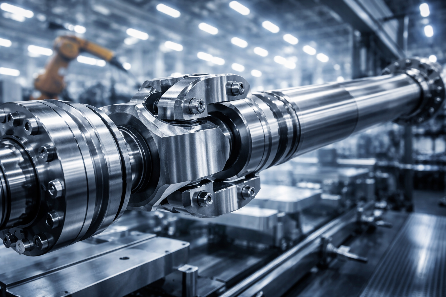
Hydropower generators represent some of the largest rotating machinery in the industrial world. The transmission system—specifically the shaft line connecting the hydraulic runner to the electrical generator—is the critical artery of these renewable energy powerhouses. Unlike horizontal setups found in thermal power plants, vertical shaft hydro turbines (Francis and Kaplan types) present a unique set of vector physics challenges.
The shaft line is not merely a torque transmission device; it is a structural column that must support the weight of the rotating assembly (runner + shaft + exciter) while resisting the immense hydraulic thrust generated by the water flow. In large-scale installations, this combined axial load can exceed several hundred tons.
Vertical Shaft Turbines (Francis & Kaplan)
Vertical configurations are the standard for medium-to-large scale hydropower plants, such as those found in the pumped storage schemes of Wales or the large dams of Scotland. The vertical orientation allows for the submergence of the runner to prevent cavitation while keeping the generator and electrical equipment dry and accessible above the tailwater level.
Francis Turbines
In Francis turbines, the water enters radially and exits axially. The shaft must withstand significant radial hydraulic forces caused by uneven pressure distributions in the scroll case, especially during partial load operations. Our shafts are engineered with high stiffness to minimize deflection under these radial loads, ensuring the runner seals do not contact the stationary wearing rings.
Kaplan Turbines
Kaplan turbines, used for lower heads, feature adjustable blades. This adds a layer of complexity: the main drive shaft is often hollow (bored) to accommodate the internal oil pipes and control rods required to actuate the blade pitch mechanism. UK pto-drive-shafts.com Co.,Ltd. specializes in manufacturing these complex, deep-hole bored shafts with high concentricity.
The Turbine-Generator Shaft Line: Anatomy of a Critical Component
The shaft line typically consists of the turbine shaft, intermediate shaft(s), and the generator shaft. The connection points—the couplings—are the most critical stress points in the system.
Critical Requirement 1: Plumbness & Concentricity
Since the shaft line can extend over 20 meters in large installations, its flexibility cannot be ignored. The alignment process is not simply about “straightness”; it is about “plumbness” relative to gravity and the hydrodynamic center.
The เพลา system must be aligned to be absolutely vertical. The runout (throw) at the guide bearing locations must be microscopic—typically requiring tolerances of less than 0.002 inches per foot (0.16 mm per meter) of shaft length. If this tolerance is exceeded, the resulting centrifugal forces will cause severe vibration, leading to guide bearing failure and potentially catastrophic damage to the generator stator.
We achieve this through precision flange facing. Our flanges are machined to be perfectly perpendicular to the shaft axis, often requiring thermal fitting or hydraulic tensioning bolts to ensure the mating surfaces act as a solid, monolithic unit.
Critical Requirement 2: Axial Thrust Transmission
The shaft acts as a tension or compression member depending on the bearing arrangement. It must transmit:
- Hydraulic Thrust: The downward force exerted by the water on the runner blades.
- Dead Weight: The mass of the runner, the shaft itself, and often the generator rotor.
This places the shaft under high compressive stress. The material selection must account for this, ensuring no buckling or deformation occurs even under “runaway” conditions where the turbine spins freely without load, generating maximum centrifugal and hydraulic forces.
Critical Requirement 3: Abrasion Resistance at the Shaft Seal
The point where the shaft passes through the turbine head cover—the Main Shaft Seal—is the frontline between the high-pressure water passage and the dry powerhouse. This area is subjected to silt, sand, and glacial flour (common in Scottish hydro schemes), which act as a grinding paste.
To combat this, UK pto-drive-shafts.com Co.,Ltd provides shafts equipped with renewable sleeves. These sleeves are coated with High-Velocity Oxygen Fuel (HVOF) applied Tungsten Carbide or Chrome Oxide ceramic layers. This creates a surface hardness exceeding 70 H
แก้ไขโดย gzl


