 Getting the measurement wrong on a PTO shaft is not simply an inconvenience — it can result in catastrophic driveline failure, expensive downtime on the farm or factory floor, and serious safety hazards for operators. Whether you are replacing a worn shaft on a tractor in Yorkshire, fitting an agricultural implement in the Welsh valleys, or specifying a gearbox input shaft for a processing plant in Birmingham, the principles of accurate PTO shaft measurement remain constant. This guide walks you through every critical dimension, from the spline profile to the overall collapsed length, and explains exactly why each measurement matters.
PTO drive shafts operate under extraordinary mechanical demands — transmitting rotational power from a tractor or engine to an implement while allowing angular displacement, telescopic adjustment, and torsional shock absorption. A shaft that is even slightly too short will pull apart under load. One that is too long will compress solid and destroy both the implement gearbox and the tractor PTO stub. Precision is not optional; it is fundamental.
Need a Custom PTO Shaft Fast?
Ever Power manufactures and supplies precision PTO drive shafts to exact specifications. UK-ready stock and bespoke manufacturing with lead times to suit your project.
Response within 24 hours — UK business hours
Why Accurate Measurement Is the Foundation of Safe PTO Operation
⚠
Collapse Hazard
A shaft that bottoms out under hydraulic lift can shatter the implement coupling or snap the tractor PTO stub. Always verify minimum collapsed length with the implement at full lift height.
🔗
Disengagement Risk
A shaft that is too short at maximum extension can disengage entirely while spinning — an instantly lethal scenario. The minimum spline engagement overlap must always be maintained.
📈
Vibration & Fatigue
Incorrect length introduces U-joint operating angles outside the designed range, generating cyclic vibration that fatigue-cracks yokes and bearing housings prematurely.
The majority of premature PTO shaft failures we see in the UK market trace back to incorrect initial specification. Operators in the East Midlands arable belt, for instance, routinely mix shafts between implements without re-measuring — a practice that works until it spectacularly does not. The geometry of PTO power transmission demands that each pairing between tractor and implement be treated as a unique engineering relationship, not a generic connector. A telescoping propeller shaft is dynamically active; it changes effective length and angle constantly as the tractor turns, crosses uneven ground, or raises its linkage. Measuring it correctly means capturing the extremes of that dynamic range, not simply measuring it in the static parked position.
The measurement process involves seven distinct parameters, and each must be correct. Spline profile, spline diameter, collapsed length, extended length, U-joint cross size, yoke type, and torque rating all interact. Miss any one, and the shaft either will not fit or will not function safely. The sections below walk you through each parameter with precision.
The Seven Measurements You Must Take
Collapsed (Compressed) Length
This is the single most important dimension, and the one most often measured incorrectly. Raise your implement or three-point linkage to its maximum height — the position at which the tractor and implement are closest together — then measure the PTO shaft from the face of the tractor yoke to the face of the implement yoke in this compressed position. This is your minimum collapsed length requirement. The actual shaft must be longer than this measurement in its fully compressed state by at least 1 to 2 inches of spline engagement safety margin. Many operators in the arable regions around Lincolnshire and Cambridgeshire mistakenly measure at ground level with the implement lowered, which gives a meaningless figure for this critical dimension.
Extended (Operational) Length
Lower the implement to its working depth — or to the lowest point it will reach during operation — and measure the yoke-to-yoke distance again. This is your maximum required extension length. The shaft must not extend beyond the point where spline overlap drops below one-third of the total spline engagement length. As a rule of thumb, ensure that at full extension the inner and outer tubes still overlap by a minimum of 6 inches (150 mm). If this overlap cannot be maintained, the shaft is too short for the application and must be replaced with a longer unit, regardless of what the collapsed length calculation might suggest. This check is especially important for front-mounted implements on longer-wheelbase tractors, a configuration increasingly common among contractors operating in the hilly terrain of Devon and Somerset.
Spline Profile & Count
The spline is the toothed male end that engages with the tractor stub shaft. There are four primary spline types used in UK agricultural and industrial settings: 1-3/8 inch 6-spline (the most common on sub-100hp tractors), 1-3/8 inch 21-spline (used on higher-torque applications above approximately 100hp), 1-3/4 inch 20-spline (for large-frame tractors and heavy implements), and metric variants including 35mm and 45mm series used on European machinery. Never guess the spline type — count the teeth on the actual tractor stub shaft using a finger-count method or a spline gauge. The diameter must also be confirmed with calipers, not estimated. Mixing a 1-3/8 inch 6-spline shaft into a 21-spline socket appears to fit loosely but will immediately fail under load, generating the characteristic rattling destruction of a free-wheeling spline interface.
Universal Joint Cross Size
The U-joint cross (or spider) is the four-armed cruciform at each end of the shaft that allows angular deflection while transmitting rotation. Cross sizes are standardised in the UK and EU markets and are described by the outer diameter of the bearing cups and the length of the cross. Common series include the 22×54, 27×74, and 30×92 metric dimensions used in agricultural PTO shafts, correlating to torque ratings of approximately 500 Nm, 1000 Nm, and 1800 Nm respectively at standard operational angles. To identify your existing cross, remove the shaft, extract the circlips, press out one bearing cup, and measure the cup outer diameter with calipers. Width measurements are straightforward with a ruler spanning across the circlip grooves on the yoke. The cross series directly determines the maximum continuous torque the shaft can safely transmit — under-specifying this dimension is one of the most common causes of catastrophic driveline failure in heavy agricultural operations across the Scottish Borders and Northern England.
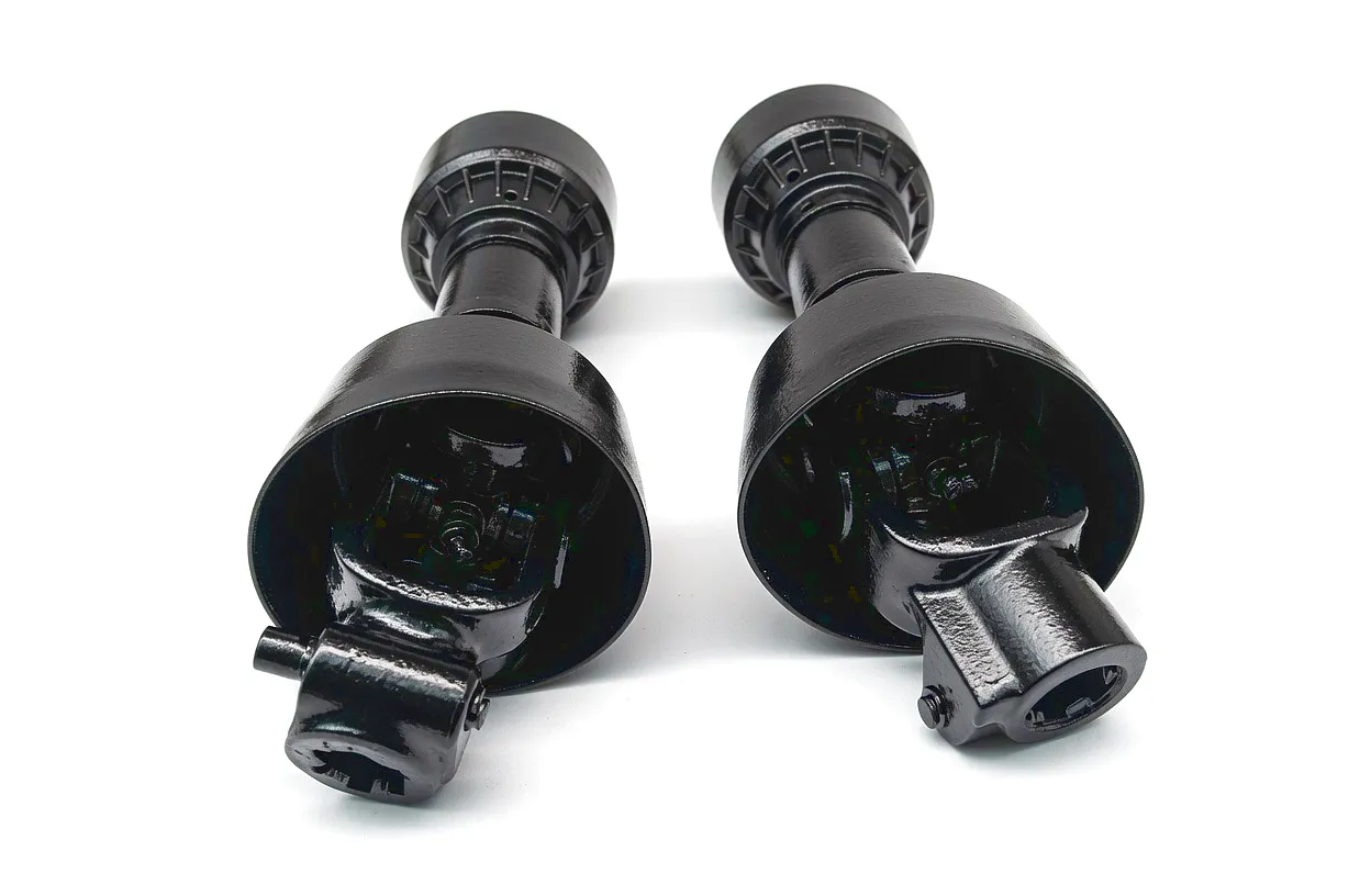
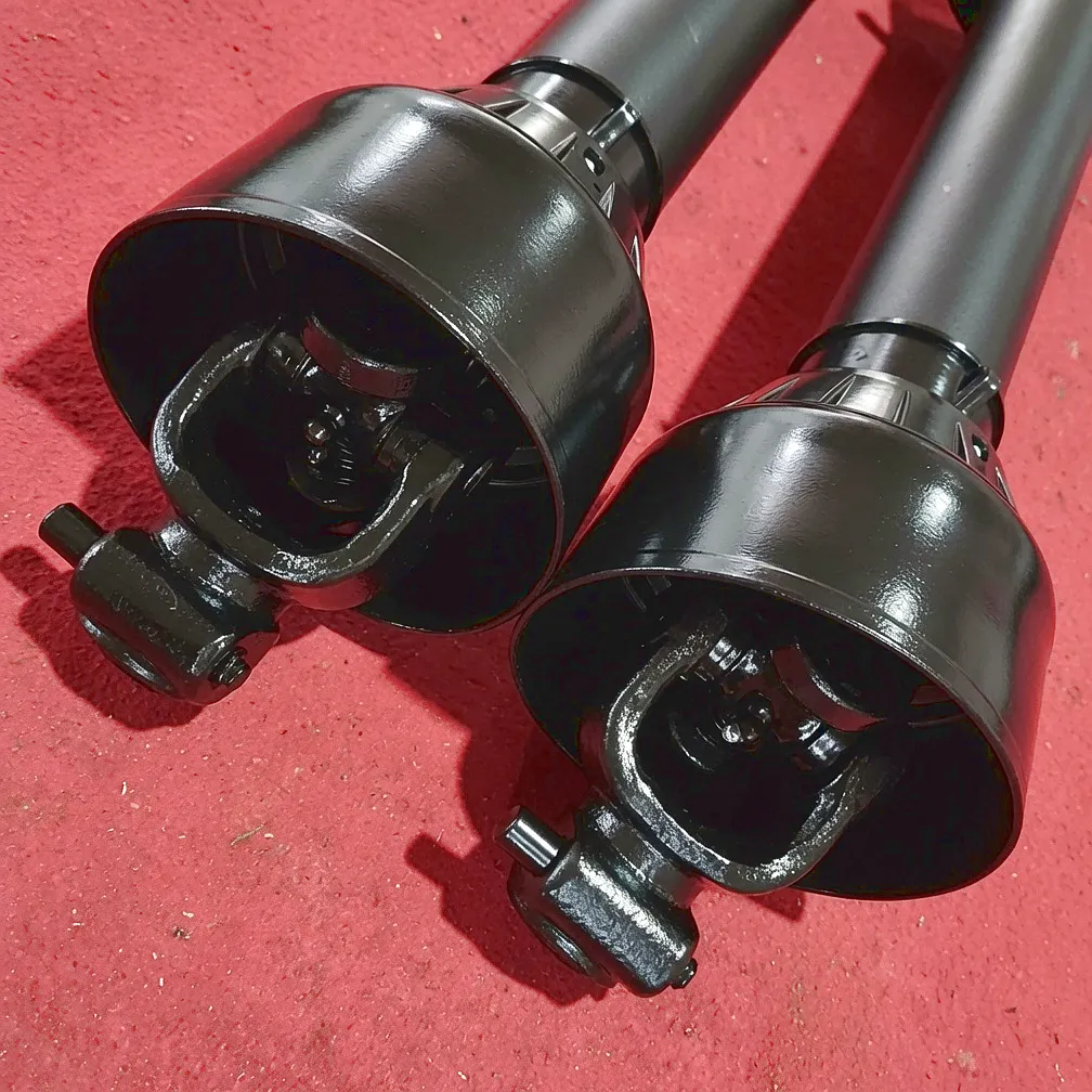
Yoke Connection Type
Yokes connect the shaft assembly to the driving and driven machines, and they come in several quite different designs that must match the mating connection precisely. Splined push-fit yokes (the most common in agricultural settings) engage directly onto splined stubs and are secured with a spring-loaded collar or pin-and-groove retainer. Quick-release yokes use a push-button or pull-ring mechanism that allows rapid connection and disconnection — these are popular on frequently-changed implements such as manure spreaders and round balers used across dairy and mixed farming enterprises. Shear-bolt yokes incorporate a deliberate mechanical weak point that sacrifices a low-cost bolt rather than allowing a blockage to destroy the gearbox. Friction-slip clutch yokes offer continuous overload protection. Each type has a different envelope dimension, engagement depth, and bolt pattern, all of which must be confirmed before ordering a replacement shaft.
Sudut Operasi
The working angle of each U-joint — the angular deviation between the input and output shafts — is a critical parameter that governs both the speed variation introduced into the driveline and the bearing life of each cross. Single-joint PTO shafts operating at angles above 15 degrees introduce velocity fluctuations that manifest as vibration and accelerated wear. The practical limit for a single-joint agricultural shaft is typically 25 to 30 degrees at intermittent loading, and around 10 degrees for continuous high-torque transmission. Double-jointed constant velocity (CV) configurations, which use two joints with an intermediate shaft and cancel out the velocity variation, extend this capability significantly. When measuring, articulate the connection through its full working range — including the worst-case turn and lift combination — and record the maximum joint angle at both ends of the shaft. This figure must fall within the rated operating envelope of the chosen cross series.
Torque Rating & PTO Speed
Every PTO drive shaft has a rated continuous torque and a peak shock torque capacity, both expressed in Newton-metres (Nm). Matching these to the power and operational characteristics of your tractor and implement is non-negotiable. The UK standard PTO speed is 540 RPM for agricultural tractors up to approximately 65kW, and 1000 RPM for larger machines — these two speeds require different shaft geometries and different rated torques at equivalent horsepower. To calculate the torque your shaft must handle, apply the formula: Torque (Nm) = Power (kW) x 9549 / RPM. A 75kW tractor at 540 RPM generates approximately 1325 Nm at the PTO stub — your shaft must be rated for this and ideally carry a service factor of 1.5 to 2.0 to accommodate shock loads. Getting this calculation wrong is the root cause of a significant proportion of shaft failures seen by agricultural engineers across the English Midlands manufacturing and farming belt.
PTO Shaft Technical Performance Reference Table
The following table provides standardised performance and dimensional data across common agricultural and industrial PTO drive shaft series. These figures represent the baseline parameters and must be confirmed against the specific shaft model for your application.
| Series / Category | Jenis Spline | Cross Size (mm) | Max Cont. Torque (Nm) | Peak Torque (Nm) | Max Speed (RPM) | Max Angle (deg.) | Tube OD (mm) | Aplikasi Lazim |
|---|---|---|---|---|---|---|---|---|
| Series 1 Light | 1-3/8″ 6-spline | 22 x 54 | 210 | 560 | 2,200 | 25 | 38 | Light mowers, seeders |
| Series 2 Standard | 1-3/8″ 6-spline | 27 x 74 | 500 | 1,500 | 1,800 | 25 | 51 | Balers, rotovators |
| Series 3 Heavy | 1-3/8″ 21-spline | 30 x 92 | 1,000 | 3,200 | 1,600 | 20 | 61 | Slurry tankers, wood chippers |
| Series 4 Extra Heavy | 1-3/4″ 20-spline | 35 x 106 | 1,800 | 5,500 | 1,000 | 15 | 76 | Crushers, heavy mixers |
| Series 5 CV Wide-Angle | 1-3/8″ 6 or 21 | 27 x 74 + CV bell | 500 | 1,800 | 1,800 | 80 (CV end) | 51 | Front implements, tight linkages |
| Industrial 1000 RPM | 1-3/4″ 20-spline | 42 x 120 | 3,000+ | 8,000+ | 1,100 | 10 | 90+ | Industrial drives, generators |
All figures are indicative. Confirm with your shaft manufacturer for certified ratings. Torque formula: T (Nm) = P (kW) x 9549 / n (RPM)
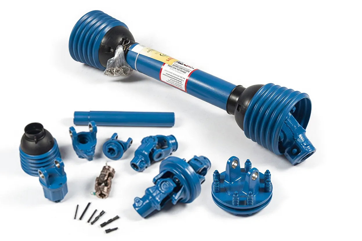
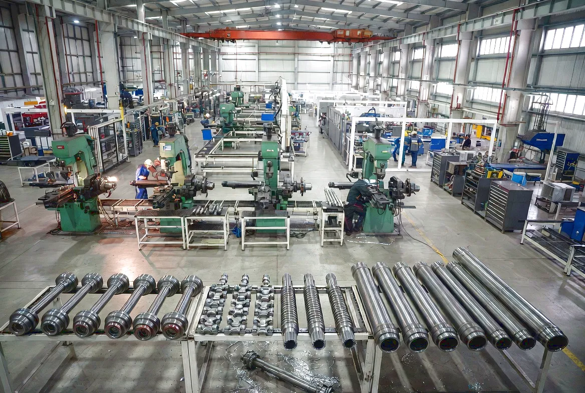
Materials, Construction & Working Principle
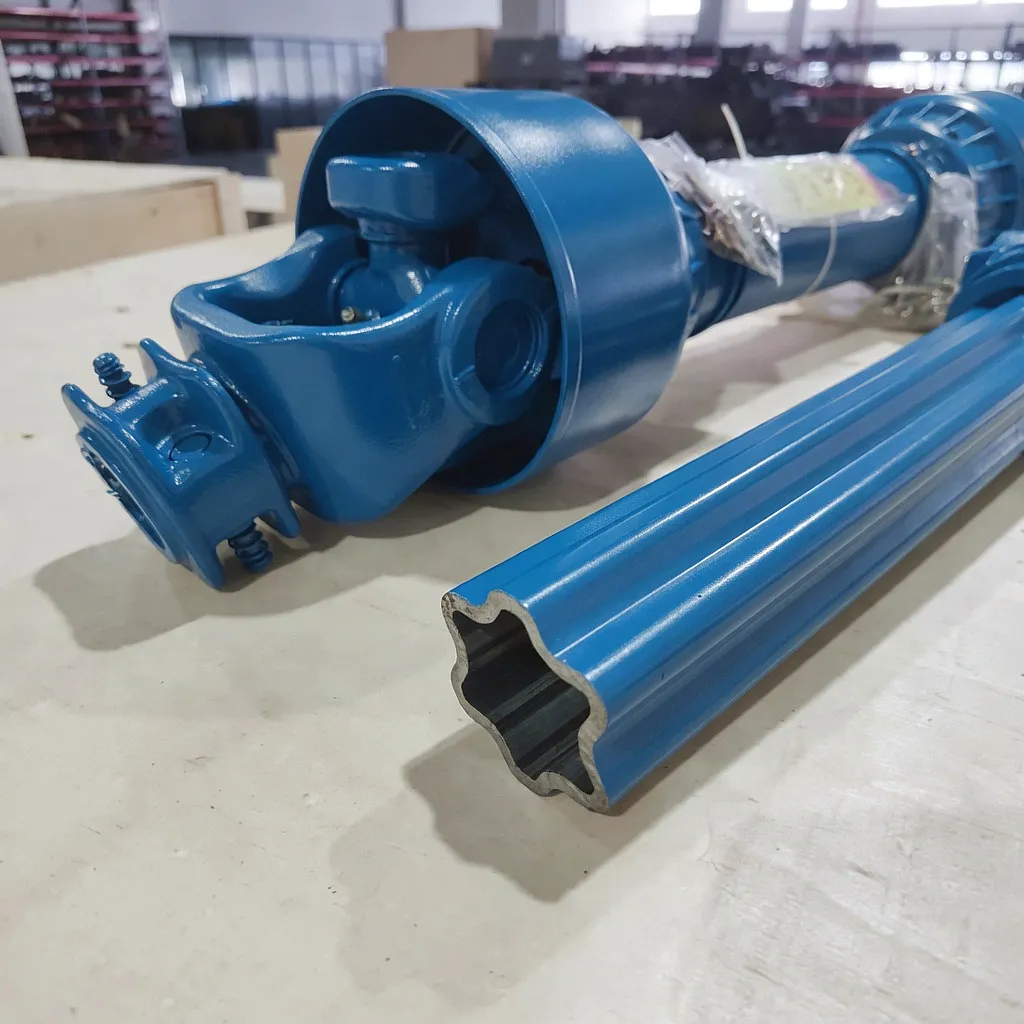
 A PTO drive shaft works on a beautifully simple mechanical principle that becomes extraordinarily demanding in practice. Rotational power generated by the tractor engine is taken at the rear stub shaft, transmitted through a series of universal joints and a telescoping tube assembly, and delivered to the gearbox input of the implement. The telescoping section — typically two interlocking tubes in a lemon, star, or barrel profile — allows the driveline to change length as the geometry between tractor and implement changes during operation.
The universal joints at each end permit angular misalignment between the tractor PTO axis and the implement input axis. At angles up to approximately 15 degrees, this angular displacement is handled efficiently. Beyond that threshold, velocity variation within each revolution — described mathematically as the second harmonic of shaft rotation — creates torsional pulses that accelerate bearing wear.
⚙ Tube Material
Cold-drawn seamless steel tube (Grade E235 or E355 to EN 10305) provides the torsional stiffness and fatigue resistance required for cyclic PTO loading. High-torque applications use thick-wall chromoly tubing (42CrMo4).
💣 Cross & Bearing
U-joint crosses are forged from 20MnCr5 or 18CrNiMo7-6 case-hardened alloy steel, achieving surface hardness of 58 to 62 HRC while maintaining a tough, impact-resistant core. Needle roller bearings in sealed cup assemblies provide the rolling interface.
🛠 Yoke & Spline
Yokes are either die-forged medium carbon steel (C45) or ductile iron GJS-600-3 for lighter applications. Spline profiles are machined to DIN 5480 or ISO 14 tolerances, providing the close sliding fit needed for telescopic function without fretting wear.
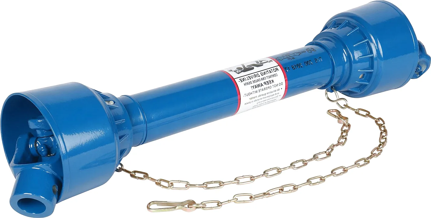
🛡 Safety Shield
The plastic or steel outer shield tube is legally mandatory under UK PUWER and HSE regulations for any powered PTO shaft accessible to operators. Polypropylene copolymer shields are UV-stabilised, resist impacts, and allow the inner shaft to rotate independently within. Guard-to-ground clearance must also be verified during measurement.
Where PTO Drive Shafts Work Hardest: UK Industrial Applications
The range of machines and processes driven by PTO shafts in the United Kingdom extends far beyond the classic tractor-and-implement pairing visible on every British farm. From the biomass processing plants of the Humber Estuary to the concrete mixing operations in the West Midlands construction corridor, PTO drive shafts form a critical link in an enormous variety of power transmission chains. Understanding the precise application context matters enormously when taking measurements, because each sector imposes its own specific demands on the shaft assembly in terms of torque signature, duty cycle, and environmental exposure.
UK Agriculture
From cereal harvesting in East Anglia to silage production in Shropshire and potato operations in Lincolnshire, the agricultural PTO shaft works year-round across balers, round balers, mowers, tedders, spreaders, sprayers, wood chippers, and post-hole borers. Seasonal variations in humidity, mud ingress, and freezing temperatures all accelerate wear on poorly specified shafts.
Construction & Groundworks
Concrete mixers, augers, compaction plates, and trench diggers used extensively on housing developments across the Yorkshire and Greater Manchester construction boom rely on robust PTO shafts rated for intermittent high-shock loading. These applications frequently demand wide-angle CV joints due to constrained site geometry.
Standby Power Generation
PTO-driven generators are widely deployed across remote rural sites, events venues, and emergency services infrastructure throughout the UK. These applications place sustained full-load demands on the shaft at constant 1000 RPM, requiring careful attention to continuous torque ratings and U-joint service intervals.
Industrial Processing
The food processing corridors around Sheffield and Birmingham, and the chemical and pharmaceutical manufacturing clusters across the North West, use PTO-style shaft assemblies to link motors, gearboxes, and process equipment. These industrial variants often specify stainless steel components and sealed bearings rated for wash-down environments.
Measurement Checklist at a Glance
- ✓ Collapsed length at maximum implement height
- ✓ Extended length at maximum implement depth
- ✓ Spline type, count, and outer diameter (both ends)
- ✓ U-joint cross dimensions (cup OD x length)
- ✓ Yoke connection type and engagement depth
- ✓ Maximum operating angle at worst-case geometry
- ✓ Required continuous and peak torque (Nm)
- ✓ PTO speed standard (540 or 1000 RPM)
Customer Success Story: Sheffield Biomass Processing
 Cabarannya: Greenfield Biomass Solutions Ltd, a Sheffield-based operator supplying wood chip fuel to district heating networks across South Yorkshire, was experiencing recurring PTO shaft failures on their Volvo BM tractor-powered Doppstadt wood chippers. The machines were running at 1000 RPM for sustained periods of 8 to 10 hours per day, six days a week. Standard catalogue replacement shafts from a local UK supplier were lasting only four to six weeks before the U-joint crosses and needle bearings showed catastrophic wear. The collapsed length of the original shafts was also incorrect for the chipper’s hydraulic feed mechanism, which brought the PTO connection geometry to an acute angle during normal chipping operation.
The Ever Power Solution: After contacting the Ever Power engineering team, Greenfield’s workshop manager provided the full set of seven measurements using the methodology described in this guide — collapsed and extended lengths, spline specification (1-3/4 inch 20-spline on both tractor stub and chipper input), U-joint cross dimensions confirming a 35 x 106 series requirement, and the critical operating angle data showing that at maximum chipper deck elevation the shaft was working at 22 degrees on the tractor-end joint. Ever Power specified a Series 4 heavy-duty shaft with 42CrMo4 tube, 35 x 106 crosses in 18CrNiMo7-6 alloy, and a double-boot sealed grease nipple arrangement designed for extended service intervals. Collapsed length was manufactured to 820mm (versus the 780mm catalogue unit that had been pulling partially off the spline), and a friction-slip clutch yoke was incorporated on the implement end to protect the chipper gearbox from blockage-induced shock loads.
The Result: Greenfield’s first two Ever Power custom shafts completed 11 months of continuous service without failure — a more than ten-fold improvement over the previous arrangement. The friction clutch eliminated three gearbox damage incidents that had previously occurred during blockages, saving an estimated GBP 18,000 in repair costs over the period. The workshop manager reports the re-greasing interval has extended from weekly to monthly, reducing planned maintenance time by over 60 hours per shaft per year. Greenfield now sources all PTO drivelines exclusively through Ever Power and has added their specification to their new equipment procurement checklist.
What Our Clients Say
★★★★★
“We specified the exact collapsed length we needed — 820mm — and the shaft arrived matching our drawings to within half a millimetre. The heavy-duty crosses have now run for nearly a year without any sign of wear. Ever Power clearly understands what sustained 1000 RPM chipper duty actually involves, which is more than we can say for most catalogue suppliers.”
James R., Workshop Manager
Greenfield Biomass Solutions Ltd, Sheffield
★★★★★
“Ever Power handled our OEM requirement for a modified yoke pattern that no other supplier would touch without a minimum order of 500 units. They came back with a prototype within three weeks and the finished batch cleared our quality audit without a single rejection. For agricultural machinery dealers in the UK market, this level of customisation responsiveness is genuinely rare.”
David H., Procurement Director
Northern Implement Distributors Ltd, Leeds
★★★★★
“We switched our slurry tanker fleet to Ever Power friction-slip clutch shafts after losing a gearbox to a blockage on a Welsh hillside in the middle of slur
suntingan oleh gzl


