Engineered in Suffolk for the Global Polymer Industry. Handling extreme torque, thermal stress, and dynamic misalignment.
The Mechanics of Torque in Polymer Processing
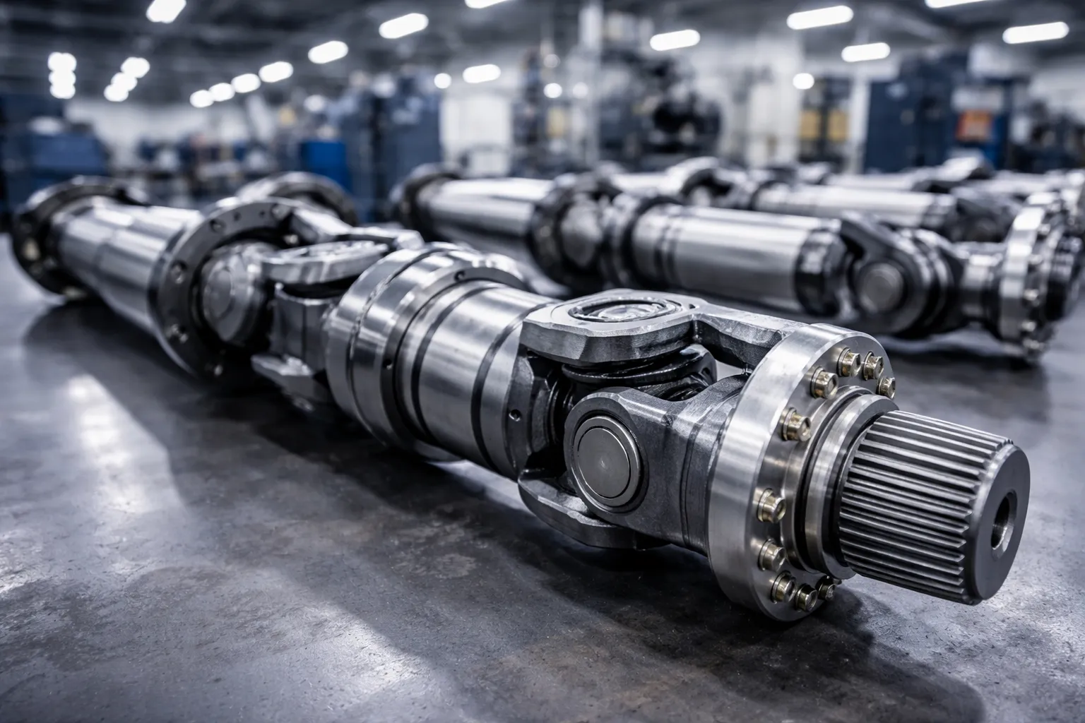
In the demanding environment of rubber and plastics manufacturing, open two-roll mills are crucial workhorse equipment. Whether used for mastication, mixing, or sheeting, the drive system is subjected to very high power loads. The core challenge lies not only in transmitting torque but also in transmitting torque under variable geometry. Unlike fixed drive systems, the front roll of the mill needs to move to adjust the “nip” or gap distance to control sheet thickness. This movement results in constant misalignment between the gearbox output and the roll neck.
Traditional single-drive systems use large gears with a fixed transmission ratio, but these often suffer from rapid wear and high noise levels. Modern industrial standards have clearly shifted towards independent drive systems, where each roll is driven by its own motor and reduction gearbox. In this system, the universal joint (cardan shaft) becomes a critical component. It must accommodate the “offset” caused by the roll movement and maintain a constant angular velocity to ensure uniform processing of the rubber compound while avoiding vibration waves that could affect the material’s surface quality.
FROM THE FIELD: A Senior Engineer’s Log
In 2019, while working on an equipment upgrade project for a tire compound manufacturer in Manchester, we encountered a challenging problem: their 26-inch grinding mill was frequently breaking down. The original coupling failed every six months due to the severe “impact load” generated when feeding cold natural rubber blocks into the roller gap. Furthermore, the operators were using an extremely high friction ratio, resulting in angular deviations exceeding 15 degrees during maintenance intervals.
Standard off-the-shelf shafts could not withstand this combination of torque peaks and angular deviations. We redesigned the solution using an 890 series shaft with an improved spline profile and 42CrMo4 heat-treated yoke, integrating a calculated shear pin system. Six months later, the maintenance manager called – not to report a failure, but to tell us that when a metal tool accidentally fell into the mixture, the shear pin broke exactly as designed, protecting their £40,000 gearbox from damage. This is why we strive for excellence in our design specifications – because the real world leaves no room for error.
Technical Specification Matrix
Our shafts are not catalog commodities; they are engineered systems. Below are the standard operational parameters for our Polymer Industry Series, designed to withstand the high-viscosity resistance of rubber compounds.
| 매개변수 ID | 기술 사양 | Metric Value / Range |
|---|---|---|
| TS-001 | 공칭 토크(Tn) | 25 kNm – 850 kNm |
| TS-002 | 피로 토크(Tfat) | 1.5 x Tn |
| TS-003 | Max Shock Torque (Tshock) | 3.0 x Tn (Instantaneous) |
| TS-004 | 플랜지 직경(A) | 225mm – 620mm |
| TS-005 | 폐쇄 길이(Lc) | 800 mm – 4500 mm |
| TS-006 | Compensation Stroke (La) | +110 mm to +450 mm |
| TS-007 | Max Operating Angle | 25 Degrees (Short duration 35) |
| TS-008 | 회전 속도(최대) | 1200 RPM (Balanced G6.3) |
| TS-009 | 스플라인 유형 | 인벌류트 스플라인 DIN 5480 |
| TS-010 | 스플라인 경도 | HRC 58-62 (유도 경화) |
| TS-011 | Cross Assembly Material | 20CrMnTi 표면 경화 |
| TS-012 | 요크 소재 | 단조 42CrMo4V |
| TS-013 | 튜브 재질 | Seamless DOM St52.3 / 34CrMo4 |
| TS-014 | 도장 사양 | Epoxy Primer + PU Topcoat (RAL 5010) |
| TS-015 | 윤활 간격 | 500 Hours (Standard) / 2000 Hours (Lip Seal) |
| TS-016 | 작동 온도 | -20°C to +180°C (High Temp Seals) |
| TS-017 | 안전 기능 | Integrated Shear Pin or Torque Limiter |
| TS-018 | 플랜지 연결 | DIN, SAE, or Hirth Serration (Face Key) |
| TS-019 | 동적 균형 조정 | ISO 1940-1 등급 G6.3 |
| TS-020 | 베어링 수명(L10h) | 25,000시간 이상 |
| TS-021 | 비틀림 강성 | 1.85 x 10^6 Nm/rad |
| TS-022 | 스윙 직경 | 200 mm – 580 mm |
| TS-023 | 축력(하중 하에서) | < 3% of Axial Load Capacity |
| TS-024 | 씰 타입 | Multi-lip Viton for abrasive dust protection |
| TS-025 | 인증 | ISO 9001:2015, ATEX (Optional) |
| TS-026 | 코팅 두께 | Min 120 microns |
| TS-027 | 용접 표준 | ISO 3834-2 |
| TS-028 | 비파괴 검사 | 100% Ultrasonic & Magnetic Particle on Yokes |
Regional Compliance: UK & European Standards
Operating heavy machinery in the UK requires strict adherence to safety regulations. Our design specifically complies with the requirements of the Provision and Use of Work Equipment Regulations 1998 (PUWER). In particular, regarding Regulation 11 (Mechanical Hazards), our shafts are equipped with integrated protective interfaces or fixed safety sleeves, allowing the shaft to rotate within a non-rotating plastic housing, significantly reducing the risk of pinching injuries.
Furthermore, we strictly follow the guidelines set out in HSG17 (Safety Guidance for the Use of Two-Roll Mills) published by the UK Health and Safety Executive (HSE). The rubber mixing process is unpredictable—”batch” mixing can lead to sudden torque surges—meaning that component failure must be predictable and controllable. We intentionally design a “weak link” (shear pin) outside the main drive area to ensure that in the event of a jam, the shaft safely breaks without causing the universal joint to rupture, thus preventing dangerous flying debris from the universal joint.
Regional Application Insights
Our engineering teams have supported installations across the UK’s industrial heartlands:
- Birmingham & The West Midlands: Supporting the automotive supply chain, where high-precision rubber sealing strips are manufactured. Requirements often focus on vibration-free transmission at high speeds.
- Leeds & Yorkshire: Heavy industry applications involving conveyor belt manufacturing. These mills require massive torque capacity (up to 500 kNm) to process thick, cold rubber slabs.
- 서퍽 및 동부 지역: Specialized pharmaceutical grade plastics, requiring contamination-free drive shafts with specialized Nickel-plated coatings to prevent corrosion and debris.
Brand Compatibility and Engineering Integrity
We understand that many facilities operate mixed fleets of machinery. Our retrofitting division is capable of manufacturing drop-in replacements for driveshafts originally supplied by other major entities. Whether your mill was originally fitted with shafts from GWB™ (Dana), GKN™, Maina™, or Voith™, we can reverse-engineer the flange interface and torque capacity to provide a functional equivalent or an upgraded heavy-duty alternative.
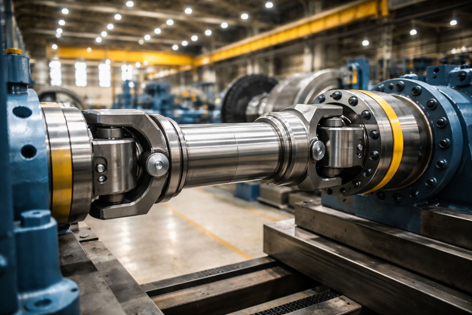
The System Approach: Gearbox Integration
A drive shaft does not exist in isolation. It is the bridge between the prime mover (Gearbox) and the load. In Open Two-Roll Mills, the gearbox is often subjected to the same punishing shock loads as the shaft. While our expertise centers on the transmission of power via the shaft, we have expanded our manufacturing capabilities to support the entire drive train.
Heavy Duty Industrial Gearboxes for Mixing Mills
Complementing our shaft technology, we manufacture and supply parallel-shaft helical gear reducers designed specifically for the rubber and plastics sector. The synergy between the gearbox and the 카르단 샤프트 is vital. A gearbox with excessive backlash can amplify the impact forces on the shaft’s cross-joints during load reversal. Conversely, a stiff, high-precision shaft requires a gearbox with robust output bearings to handle the radial loads induced by the shaft’s weight and angle.
Series ZLYJ and ZSYJ High-Precision Reducers:
Our gearboxes are engineered with case-hardened alloy steel gears (20CrMnTi), precision ground to ISO Grade 6. This ensures low noise and high efficiency (>96%). For Two-Roll Mills, we recommend our specialized output shaft configurations which feature reinforced bearing housings to accept the “overhung load” created by the heavy cardan shaft.
By sourcing both the gearbox and the connecting shaft from a single engineering partner, you eliminate the “tolerance stack-up” issues that often plague multi-vendor assemblies. We calculate the torsional critical speed of the entire system—Motor + Gearbox + Shaft + Roll—to ensure that the operating speed avoids resonance frequencies that destroy equipment.
Maintenance & Longevity: The Human Factor
Technology is only as good as its maintenance. In our site visits across the UK, we often see premature failure caused not by design flaws, but by lubrication neglect. The harsh environment of a rubber mill—filled with carbon black dust and high ambient heat—is the enemy of the needle bearing.
We have introduced the “Visual-Lube” system on our UK-spec shafts. This simple yet effective modification involves purging channels that clearly show when old grease has been fully expelled and replaced by fresh lubricant. For the sliding spline—the component that accommodates the mill’s nip adjustment—we use a Molybdenum Disulfide based coating (MoS2) on the mating surfaces to prevent galling (cold welding) during high-torque adjustments.
자주 묻는 질문
How do I measure for a replacement mill shaft?
Do not measure the shaft while it is installed if possible. We need the “Flange-to-Flange” compressed length (shortest state) and the required extension length. Also, measure the Pilot Diameter (spigot) and the Bolt Circle Diameter (PCD) on the flange face.
Why does my shaft vibrate during sheet adjustment?
This is often due to “Phase Mismatch.” The yokes at both ends of the shaft must be aligned in the same plane. If the shaft has been taken apart and reassembled incorrectly (splines offset by one tooth), the non-uniform velocity will cause severe vibration.
Can you upgrade my mill to handle higher torque?
Yes. We can often switch to a larger “Series” of cross-joint (e.g., from 225mm to 250mm swing diameter) while machining custom flanges to fit your existing gearbox and roll neck, providing a 20-30% increase in torque capacity.
Industry News: UK Manufacturing
Suffolk, January 2026: With the rising cost of energy, UK rubber manufacturers are increasingly auditing their drive trains for efficiency. Misaligned or worn universal joints can result in a 3-5% energy loss due to friction and heat generation. Replacing legacy friction bearings with modern roller-bearing cardan shafts is becoming a key strategy in reducing the carbon footprint of heavy processing plants.
gzl님이 편집했습니다.


