Executive Engineering Summary:This technical paper explores the hydrodynamic and mechanical challenges faced by universal joints in the harsh environments of UK ports such as Felixstowe and Southampton. We analyze the dynamic differences in gantry crane travel mechanisms, the fatigue limits of the main hoisting system, and provide a comprehensive comparison of torque transmission solutions compliant with British Standards (BS) and ISO 12944 corrosion resistance standards.
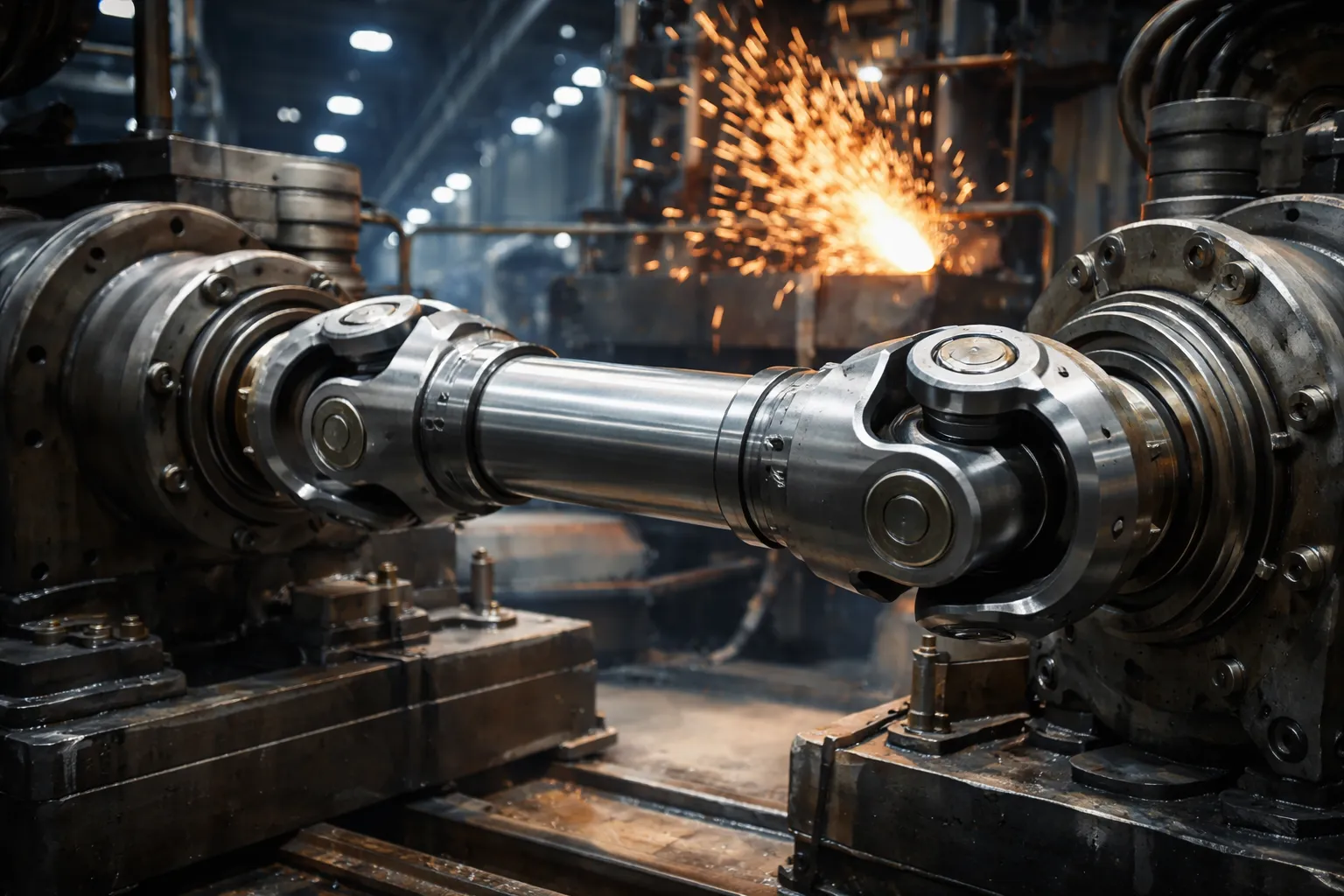
Quayside cranes are the guardians of global trade, these colossal structures determining the lifeline of the UK island economy. From the bustling container terminals of London’s gateway ports to the deep-water berths of Liverpool, the efficiency of these giant cranes depends on the smooth transmission of torque. At the heart of this power transmission lies the industrial universal joint – an often-overlooked component until failure leads to downtime, costing thousands of pounds in demurrage fees per hour.
The Kinetic Architecture of STS Cranes: Where Cardan Shafts Reside
The STS crane is not a singular machine but a complex assembly of independent kinematic systems. Each system—Gantry Travel, Main Hoist, Trolley Travel, and Boom Hoist—imposes unique stress vectors on the drive shafts. Understanding these vectors is crucial for selecting the correct universal joint shaft.
Gantry Travel Mechanism: The Challenge of Synchronization
The gantry travel mechanism is responsible for moving the entire crane structure along the quay rails. Given the immense span of modern Super Post-Panamax cranes (often exceeding 30 to 50 meters) and the flexible nature of the steel portal frame, the drive system has evolved significantly.
Centralized Drive Systems: The Legacy Challenge
In legacy designs and specific heavy-duty configurations found in older terminals across the UK and Europe, a centralized drive architecture is employed. A massive central motor, positioned on the portal beam, distributes power to the bogies on either side via long-span drive shaft lines.
- Structural Deformation: The crane’s portal frame acts as a flexible beam. Under wind loads (common in the English Channel) and lifting loads, the frame twists. This creates significant relative displacement between the central gearbox and the wheel bogies.
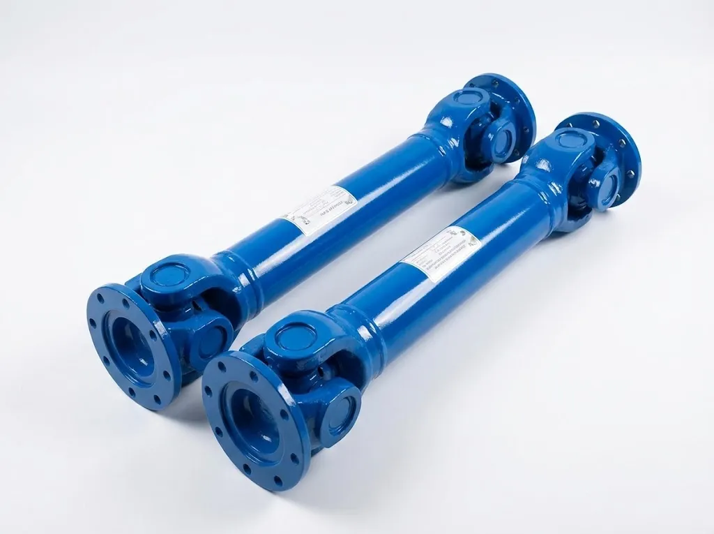
- Floating Shaft Design: To compensate, the terminal drive shafts are designed as “floating shafts.” These utilize a double-Cardan arrangement with a long-stroke splined telescoping section. This setup allows the shaft to transmit torque while simultaneously articulating to absorb the frame’s deflection and extending/compressing to accommodate the changing distance.
- Critical Speed Issues: Long spans introduce the risk of “whirling.” Engineers must calculate the critical speed carefully. Often, intermediate support bearings are required, or large-diameter tubes are used to increase stiffness without adding excessive mass.
Individual Wheel Drive: The Modern Standard
Modern terminals, aiming for redundancy and precision control, favor individual wheel drives. Here, the motor and gearbox are mounted directly at the bogie.
- Short-Coupled Designs: Even in this direct setup, rigid couplings are often unsuitable due to the articulation of the bogie required to handle uneven quay rails. Super-short Cardan shafts (e.g., comparable to GWB 587 series) are essential.
- Fatigue from Cyclic Loading: Gantry motion involves frequent starting, stopping, and reversing against high inertia and wind resistance (especially in the gusty conditions of Scotland or Northern Ireland). The shafts must be rated for high-cycle fatigue.
Main Hoist Mechanism: The Safety-Critical Core
The main hoist lifts the container. This is a safety-critical application under UK LOLER regulations. The drive train typically runs from the motor to a high-speed brake, then via a Cardan shaft to the gearbox and drum.
- Heavy Duty Classification: These shafts must handle shock loads caused by “snagging” (when a container catches in the ship’s cell guides) and emergency braking. A Service Factor (SF) > 2.5 is standard engineering practice.
- Baseframe Flexing: Under a 60-tonne load, the machinery house floor flexes. A rigid coupling would destroy the motor bearings instantly. The Cardan shaft isolates these radial forces.
Technical Parameters for UK & European Port Applications
Designing for the UK market requires adherence to specific technical parameters that account for our maritime climate and heavy usage patterns. Below is a generated dataset representing the typical specifications for a heavy-duty STS Gantry Travel Shaft.
| ID Parameter | Technical Attribute | Spesifikasi / Nilai | Catatan Teknik |
|---|---|---|---|
| 01 | Torsi Nominal (Tn) | 45 kNm – 120 kNm | Baseload requirement |
| 02 | Torsi Kelelahan (Tdw) | 65 kNm | Reversing load capacity |
| 03 | Torsi Putus | > 350 kNm | Ultimate failure limit |
| 04 | Diameter Flensa | 225mm – 350mm | DIN 15450 / ISO 7646 standard |
| 05 | Jumlah Lubang Flensa | 8 or 10 | High-tensile bolt mating |
| 06 | Diameter Lubang Baut | 18mm – 22mm | Fit tolerance H7 |
| 07 | Sudut Artikulasi (Maks) | 15° – 25° | Compensates for bogie tilt |
| 08 | Length Compensation (La) | 120mm – 400mm | Spline stroke capability |
| 09 | Compressed Length (Lz) | Variable (Custom) | Site-specific measurement |
| 10 | Diameter Tabung | 140mm x 10mm | Seamless drawn steel tube |
| 11 | Kelas Material | 42CrMo4 / SAE 4140 | Quenched and Tempered |
| 12 | Spline Treatment | Rilsan® / Nylon Coating | Reduces friction & fretting corrosion |
| 13 | Jenis Segel | Double-Lip Viton (FKM) | Resistant to saline/ozone |
| 14 | Standar Pengecatan | ISO 12944 C5-M | Marine environment durability |
| 15 | Paint Thickness (DFT) | 320 microns | Epoxy + Polyurethane topcoat |
| 16 | Kualitas Keseimbangan Dinamis | G16 (ISO 1940) | Low speed, high mass |
| 17 | Kisaran Suhu Operasional | -20°C to +50°C | Suitable for UK winters/summers |
| 18 | Pelumasan | Kompleks Litium EP2 | Water washout resistant |
| 19 | Service Factor (Application) | 2.0 – 2.5 | Heavy shock load class |
| 20 | Cross Kit Hardness | 58-62 HRC | Case hardened |
| 21 | Diameter Ayunan | 280mm | Clearance check required |
| 22 | Berat | Approx. 180kg | Tergantung pada panjangnya |
| 23 | Connection Type | Face Key / Friction Grip | Prevents flange slip |
| 24 | Siklus Pemeliharaan | 3 Months / 500 Hrs | Re-greasing interval |
| 25 | Jaminan | 12 – 24 Months | Standard industrial terms |
| 26 | Compliance | CE, UKCA, LOLER | UK regulatory alignment |
| 27 | Production Origin | UK / Global OEM | Traceability required |
Regional Adaptation: Local SEO and Compliance
For operations within the UK, particularly those serving key ports such as Grimsby, Immingham, Teesport, and Milford Haven, compliance with local regulations is essential. The damp, saline air of the British Isles (C5-M environment) requires bearings with superior corrosion resistance compared to those used in drier regions.
UK & Neighbouring Markets (Ireland, Netherlands, France, Germany)
In the North Sea region (including the UK, Rotterdam, Hamburg, and Antwerp), paint and coating standards are very strict. We use a multi-layer coating system: zinc-rich primer, micaceous iron oxide intermediate coat, and high-gloss polyurethane topcoat, to resist UV radiation and salt spray corrosion. Furthermore, all newly installed equipment in the UK must comply with the Machinery Supply (Safety) Regulations 2008 and obtain UKCA certification.
Global Context: The Top 30 Maritime Nations
From automated terminals in China (Shanghai, Ningbo) and Singapore to bulk cargo handling ports in Australia (Port Hedland) and Brazil (Santos), the fundamental physical principles of torque transmission remain the same, but the environmental factors vary considerably. In the Middle East (Dubai, Jeddah), dust ingress is a major failure mode, requiring the use of special labyrinth seals. In Scandinavia (Norway, Sweden), low-temperature steel (with Charpy impact testing at -40°C) must be used to prevent brittle fracture.
Brand Comparison and Market Position
In the high-stakes world of port machinery, reliability is the currency of choice. While several giants dominate the landscape, UK pto-drive-shafts.com Co.,Ltd. offers a compelling alternative focused on agility and customization.
- Voith (Germany): Renowned for their high-capacity CH series. Their engineering is impeccable, often setting the DIN standard. However, lead times for replacement units can be lengthy for non-standard lengths. Our UK-based assembly allows for rapid turnaround of custom-length shafts that meet equivalent torque capacities.
- Dana / GWB (USA/Germany): The 687/587 series are ubiquitous. They excel in spline coating technology. We utilize similar Rilsan-coating technologies on our splines to match this fretting resistance, offering a cost-effective alternative for fleet maintenance managers in Liverpool and Bristol.
- Maina (Italy): Common in Mediterranean equipment. Known for robust gear couplings as well. We provide drop-in replacements for Maina universal shafts, ensuring bolt-hole compatibility and torque ratings are matched or exceeded.
Critical Spare Parts and Consumables Ecosystem
A drive shaft is only as reliable as its weakest sub-component. For port maintenance managers, maintaining a strategic inventory of the following is essential:
- Cross Assemblies (Spider Kits): The heart of the joint. Includes the trunnion, needle bearing cups, and seals. Failure here is catastrophic.
- Flange Bolt Kits: High-tensile (Grade 10.9 or 12.9) bolts are single-use items. Once torqued to yield, they should not be reused during maintenance.
- Flensa Pendamping: Often wear at the face key interface.
- Bantalan Penopang Tengah: For long-span gantry drives, these pillow blocks absorb vibration and weight.
Operational Characteristics of the STS Scene
The STS environment is defined by Intermittency and Intensity. Unlike a turbine that runs at constant speed, a crane drive shaft sees:
- Zero to 100% Torque in Milliseconds: The electrical drive systems of modern cranes impose massive starting torques.
- Skewing Loads: As a gantry crane moves, one side often lags slightly behind the other (skewing). The control system corrects this, but the drive shafts absorb the physical stress of this realignment.
- Salt Crystallization: On static grease points, salt crystals can form, acting like grinding paste if seals are breached.
Personal Experience: A Case from the Port of Felixstowe
By Senior Field Engineer, G.L.
I remember receiving an emergency repair call from Felixstowe Port one winter. A catastrophic failure had occurred in the boom hoisting drive of a Level 1 gantry crane. The original shaft, installed ten years prior, had seized due to insufficient lubrication and seal failure. Salt spray corrosion had seized the internal splines completely. When the boom was lowered, the shaft couldn’t compress, acting like a solid ramrod, ultimately causing the gearbox output shaft to break.
We designed a new replacement shaft with Rilsan-coated splines and a custom-designed double-lip seal. We also added a remote lubrication line to the spline grease nipple, allowing maintenance personnel to safely lubricate the splines from the walkway without needing a cherry picker. Five years later, this shaft is still functioning perfectly with no play whatsoever. This incident taught us that ease of maintenance is just as important as the mechanical properties of the steel itself.
The Complementary Role of Gearboxes in Port Machinery
Although the driveshaft is responsible for transmitting power, the industrial gearbox is the torque amplifier that makes heavy lifting operations possible. At pto-drive-shafts.com Ltd. in the UK, we understand that the drivetrain is a complete system. Gearbox failure can lead to vibrations, which in turn can damage the driveshaft; similarly, vibrations in the driveshaft can damage the gearbox bearings.
The Symbiosis of Shaft and Gearbox
In an STS crane, the gearbox (typically a helical or bevel-helical unit) reduces the high speed of the electric motor to the high torque required for hoisting or travel. The Cardan shaft connects these units. If the gearbox has excessive backlash due to gear wear, this shock load is hammered into the universal joints of the shaft every time the crane reverses direction. Conversely, if a Cardan shaft is out of balance or has worn U-joints, it transmits high-frequency radial loads into the gearbox output shaft, leading to premature seal failure and bearing collapse.
Gearbox Solutions for Port Applications
We recommend and supply high-performance gearboxes tailored for the maritime sector. Our range covers:
- Crane Duty Helical Gearboxes: Designed with reinforced housings to withstand the twisting forces of the crane frame. Case-hardened gears ground to DIN 6 quality ensure quiet operation and high efficiency (98%+ per stage).
- Kotak Gigi Planet: Often used in winch drums due to their compact density. We supply units that integrate seamlessly with our high-torque Poros kardan.
- Maintenance & Retrofit: We offer drop-in replacement gearboxes for legacy cranes where original parts are obsolete. We match the ratio, thermal rating, and footprint, often upgrading the internal metallurgy to modern standards.
Selecting the right gearbox involves calculating the thermal rating (crucial in hot climates like Dubai or Santos) and the mechanical rating (crucial for shock loads). We ensure that the service factors of the gearbox and the Poros kardan are aligned, preventing a ‘weakest link’ scenario in the driveline.
Artificial Intelligence in Manufacturing and Quality Assurance
Our production process leverages AI-driven quality control. Automated optical inspection systems scan the needle bearings for micron-level defects before assembly. Finite Element Analysis (FEA) simulations, powered by machine learning algorithms, allow us to predict the fatigue life of our shafts under specific port load cycles, optimizing the design before metal is even cut.
This automated verification ensures that every shaft leaving our Bury St Edmunds facility meets the stringent requirements of the UKCA and ISO standards, providing our clients with documented assurance of reliability.
Note: Technical parameters and application guidelines provided herein are based on general industry standards (DIN, ISO, AGMA) and typical STS crane configurations. Specific installations may vary. Consult with our engineering team for precise calculations. All third-party trademarks (GKN, Voith, etc.) are acknowledged as the property of their respective owners and are mentioned for comparative reference only.
UK pto-drive-shafts.com Co.,Ltd. | Address: Bury St Edmunds, Suffolk IP32 7LX, UK | Email: [email protected]
edit by gzl


