
Tuotekuvaus
Customized pto drive shaft for rotavators
1. Tubes or Pipes
We’ve already got Triangular profile tube and Lemon profile tube for all the series we provide.
And we have some star tube, splined tube and other profile tubes required by our customers (for a certain series). (Please notice that our catalog doesnt contain all the items we produce)
If you want tubes other than triangular or lemon, please provide drawings or pictures.
2.End yokes
We’ve got several types of quick release yokes and plain bore yoke. I will suggest the usual type for your reference.
You can also send drawings or pictures to us if you cannot find your item in our catalog.
3. Safety devices or clutches
I will attach the details of safety devices for your reference. We’ve already have Free wheel (RA), Ratchet torque limiter(SA), Shear bolt torque limiter(SB), 3types of friction torque limiter (FF,FFS,FCS) and overrunning couplers(adapters) (FAS).
4.For any other more special requirements with plastic guard, connection method, color of painting, package, etc., please feel free to let me know.
Ominaisuudet:
1. We have been specialized in designing, manufacturing drive shaft, steering coupler shaft, universal joints, which have exported to the USA, Europe, Australia etc for years
2. Application to all kinds of general mechanical situation
3. Our products are of high intensity and rigidity.
4. Heat resistant & Acid resistant
5. OEM orders are welcomed
Our factory is a leading manufacturer of PTO shaft yoke and universal joint.
We manufacture high quality PTO yokes for various vehicles, construction machinery and equipment. All products are constructed with rotating lighter.
We are currently exporting our products throughout the world, especially to North America, South America, Europe, and Russia. If you are interested in any item, please do not hesitate to contact us. We are looking CZPT to becoming your suppliers in the near future.
| Tyyppi: | Haarukka |
|---|---|
| Käyttö: | Maataloustuotteiden jalostus, viljelysmaan infrastruktuuri, maanmuokkaus, puimuri, kylvö ja lannoitus, viljan puinti, puhdistus ja kuivaus |
| Materiaali: | hiiliteräs |
| Mukauttaminen: |
Saatavilla
| Mukautettu pyyntö |
|---|
.shipping-cost-tm .tm-status-off{tausta: ei mitään;täyte:0;väri: #1470cc}
| Toimituskulut:
Arvioitu rahti yksikköä kohden. |
toimituskuluista ja arvioidusta toimitusajasta. |
|---|
| Maksutapa: |
|
|---|---|
|
Ensimmäinen maksu Täysi maksu |
| Valuutta: | US$ |
|---|
| Palautus ja hyvitykset: | Voit hakea hyvitystä 30 päivän kuluessa tuotteiden vastaanottamisesta. |
|---|
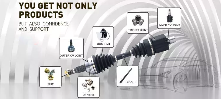
Mitkä huoltotoimenpiteet ovat olennaisia voimanottoakseleiden käyttöiän pidentämiseksi?
PIT-vetoakseleiden käyttöiän pidentämiseksi ja optimaalisen suorituskyvyn varmistamiseksi säännölliset huoltotoimenpiteet ovat välttämättömiä. Näitä huoltotoimenpiteitä noudattamalla käyttäjät voivat estää ennenaikaisen kulumisen, tunnistaa mahdolliset ongelmat varhaisessa vaiheessa ja maksimoida vetoakselin käyttöiän. Tässä on joitakin tärkeitä huoltotoimenpiteitä, jotka on otettava huomioon:
1. Voitelu:
Oikea voitelu on ratkaisevan tärkeää voimanottoakselien sujuvan toiminnan ja pitkän käyttöiän kannalta. Voitele säännöllisesti vetoakselin murrosnivelet, urat ja muut liikkuvat osat valmistajan suositusten mukaisesti. Valitse korkealaatuinen voiteluaine, joka sopii tiettyyn käyttötarkoitukseen ja ympäristöolosuhteisiin. Voitelu auttaa vähentämään kitkaa, estämään liiallista kulumista ja suojaamaan korroosiolta.
2. Tarkastus:
Säännölliset silmämääräiset tarkastukset ovat tärkeitä voimanottoakselin kulumisen, vaurioiden tai linjausvirheiden havaitsemiseksi. Tarkasta voimansiirtoakseli ja sen osat halkeamien, kolhujen, löysien pulttien tai liiallisen kulumisen merkkien varalta. Kiinnitä huomiota murrosniveliin, uriin, suojaukseen ja turvaominaisuuksiin. Jos havaitset ongelmia, ryhdy viipymättä korjaamaan ne lisävaurioiden estämiseksi ja turvallisen käytön varmistamiseksi.
3. Vääntömomentin tarkistukset:
Tarkista säännöllisesti voimanottoakselia ja sen osia kiinnittävien kiinnikkeiden, kuten pulttien ja muttereiden, kiristysmomentti. Tärinä ja normaali käyttö voivat saada nämä kiinnikkeet löystymään ajan myötä, mikä voi johtaa linjausvirheisiin tai vaurioihin. Käytä momenttiavainta varmistaaksesi, että kiinnikkeet on kiristetty oikein valmistajan ohjeiden mukaisesti. Säännölliset momentin tarkastukset auttavat ylläpitämään voimanottoakselin kokoonpanon eheyttä ja vakautta.
4. Kohdistus:
Oikean linjauksen ylläpitäminen voimanottoakselin, ensisijaisen voimanlähteen ja työlaitteen välillä on välttämätöntä tehokkaan voimansiirron ja liiallisen kulumisen estämiseksi. Tarkista nivelakselin linjaus säännöllisesti ja varmista, että se on suorassa ja oikein kiinni liitoksissaan. Linjausvirhe voi aiheuttaa tärinää, lisääntynyttä rasitusta ja ennenaikaista vikaantumista. Tee tarvittavat säädöt oikean linjauksen saavuttamiseksi.
5. Murtotapin tai vääntömomentin rajoittimen vaihto:
Jos voimanottoakselissa on turvaominaisuutena murtotappi tai vääntömomentin rajoitin, on tärkeää vaihtaa nämä komponentit, kun ne ovat aktivoituneet tai vaurioituneet. Murtotapit ovat uhrautuvia komponentteja, jotka rikkoutuvat liiallisen vääntömomentin vaikutuksesta ja suojaavat vetoakselia ja siihen kytkettyjä laitteita. Vaihda murtotappi tai vääntömomentin rajoitin oikeanlaiseen ja valmistajan suosittelemaan osaan, jotta turvallisuus ja asianmukainen toiminta pysyvät voimassa.
6. Suojaus ja vartiointi:
Tarkista voimanottoakselin suojaus säännöllisesti varmistaaksesi, että ne ovat ehjät ja hyvässä kunnossa. Nämä suojat on suunniteltu estämään kosketus liikkuviin osiin ja vähentämään sotkeutumis- tai loukkaantumisriskiä. Vaihda kaikki vaurioituneet tai puuttuvat suojat viipymättä käyttäjän turvallisuuden ylläpitämiseksi ja estääksesi roskien pääsyn voimanottoakseliin.
7. Ympäristönsuojelu:
Ota huomioon voimansiirtoakselin käyttöolosuhteet ja ryhdy asianmukaisiin toimenpiteisiin sen suojaamiseksi. Jos voimansiirtoakseli altistuu kosteudelle, lialle tai syövyttäville aineille, puhdista se säännöllisesti ja käytä asianmukaisia pinnoitteita tai suojatoimenpiteitä ruosteen ja korroosion estämiseksi. Varmista lisäksi, että voimansiirtoakseli säilytetään kuivassa ja puhtaassa ympäristössä, kun sitä ei käytetä.
8. Valmistajan ohjeet:
Noudata voimanottoakselin valmistajan antamia huolto-ohjeita. Nämä ohjeet voivat sisältää erityisiä huoltovälejä, suositeltuja voiteluaineita, kiristysmomentteja ja muita tärkeitä ohjeita. Valmistajan ohjeiden noudattaminen varmistaa, että voimansiirtoakseli huolletaan sen suunnittelun ja teknisten tietojen mukaisesti, mikä maksimoi sen käyttöiän ja suorituskyvyn.
Toteuttamalla nämä olennaiset huoltotoimenpiteet käyttäjät voivat pidentää merkittävästi voimanottoakseleiden käyttöikää. Säännöllinen voitelu, tarkastukset, vääntömomentin tarkastukset, linjaustarkastukset, turvaominaisuuksien oikea-aikainen vaihtaminen, asianmukainen suojaus, ympäristönsuojelu ja valmistajan ohjeiden noudattaminen edistävät kaikki voimanottoakselin pitkäikäisyyttä, luotettavuutta ja turvallista käyttöä.
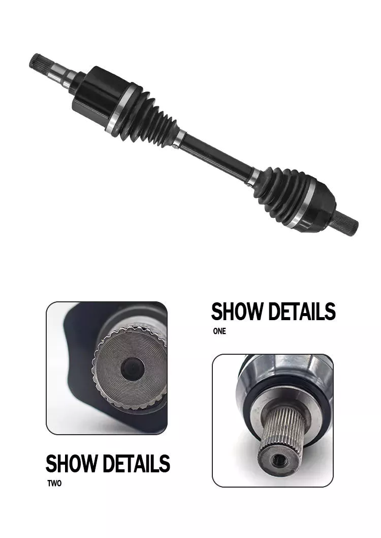
Can PTO drive shafts be customized for specific machinery and power requirements?
Yes, PTO (Power Take-Off) drive shafts can be customized to suit specific machinery and power requirements. Manufacturers often offer customization options to ensure that the PTO drive shafts meet the unique needs of different applications. Customization can involve various aspects of the drive shaft design and specifications, including:
1. Length:
The length of the PTO drive shaft can be customized to match the distance between the power source and the driven equipment. This ensures proper fit and alignment, preventing excessive tension or compression in the drive shaft. Customizing the length allows for optimal power transfer and helps accommodate specific machinery setups and configurations.
2. Connection Type:
PTO drive shafts can be customized with different connection types to match the specific requirements of the machinery. Various connection methods are available, such as splined connections, flange connections, and quick-detach mechanisms. Customizing the connection type ensures compatibility and facilitates easy attachment and detachment of the drive shaft to the power source and driven equipment.
3. Power Rating:
Customization of the power rating involves selecting appropriate components and materials to handle the specific power requirements of the machinery. This includes considering factors such as torque capacity, speed ratings, and the type of power transmission (e.g., mechanical, hydraulic). By customizing the power rating, manufacturers can ensure that the PTO drive shaft is capable of effectively transferring the required power without compromising performance or safety.
4. Protective Features:
PTO drive shafts can be customized with additional protective features to enhance safety and durability. These features may include guards, shields, or covers that prevent contact with the rotating shaft and its components. Customized protective features help mitigate the risk of accidents and increase the longevity of the drive shaft by shielding it from external elements, debris, and potential damage.
5. Material Selection:
The choice of materials used in the construction of PTO drive shafts can be customized based on specific requirements. Different materials offer varying levels of strength, durability, and resistance to factors such as corrosion or extreme temperatures. By selecting the appropriate materials, manufacturers can optimize the performance and reliability of the drive shaft for the intended application.
6. Environmental Considerations:
Customization of PTO drive shafts can take into account specific environmental factors. For example, if the machinery operates in a corrosive or hazardous environment, manufacturers can provide coatings or materials that offer increased resistance to corrosion or chemical exposure. Considering the environmental conditions helps ensure that the drive shaft can withstand the challenges presented by the operating environment.
7. Standardien noudattaminen:
Customized PTO drive shafts can be designed and manufactured to comply with relevant industry standards and regulations. Manufacturers can ensure that the customized drive shafts meet the required safety, performance, and dimensional specifications. Compliance with standards provides assurance of compatibility, reliability, and safety when integrating the customized drive shafts into specific machinery.
By offering customization options, manufacturers can tailor PTO drive shafts to suit the unique requirements of different machinery and power applications. This flexibility allows for optimal integration, improved performance, and enhanced safety. It is important to consult with the manufacturer or a qualified expert to determine the appropriate customization options based on the specific machinery and power requirements.
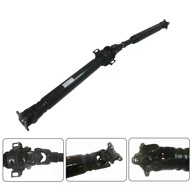
Can you explain the components and function of a PTO drive shaft system?
A PTO (Power Take-Off) drive shaft system consists of several components that work together to transfer power from a primary power source, such as a tractor or engine, to various implements or machinery. Each component plays a specific role in ensuring the efficient and reliable transmission of rotational power. Here’s a detailed explanation of the components and their functions within a PTO drive shaft system:
1. Primary Power Source:
The primary power source is typically a tractor or engine equipped with a PTO output shaft. This shaft generates rotational power from the engine’s crankshaft or transmission, acting as the starting point for power transmission.
2. PTO Output Shaft:
The PTO output shaft is a rotating shaft located on the primary power source, specifically designed to transfer power to external devices. It is typically located at the rear of a tractor and may have various spline configurations to accommodate different types of PTO drive shafts.
3. PTO Drive Shaft:
The PTO drive shaft is the main component of the system, responsible for transmitting power from the primary power source to the implement or machinery. It consists of a rotating shaft with splines at both ends. One end connects to the PTO output shaft, while the other end connects to the input shaft of the implement. The drive shaft rotates at the same speed as the primary power source, effectively delivering power to the implement.
4. Splined Connections:
The splined connections on the PTO drive shaft and the PTO output shaft of the primary power source provide a secure and robust connection. These splines ensure proper alignment and torque transmission between the two shafts, enabling efficient power transfer while accommodating varying distances and alignments.
5. Safety Guards and Shields:
PTO drive shaft systems often incorporate safety guards and shields to protect operators from potential hazards associated with rotating components. These guards and shields cover the rotating parts of the drive shaft, reducing the risk of entanglement or contact during operation.
6. Telescoping or Sliding Mechanism:
Some PTO drive shafts feature a telescoping or sliding mechanism. This allows the drive shaft to be adjusted in length, accommodating different distances between the primary power source and the implement. The telescoping or sliding mechanism ensures proper alignment and prevents excessive tension or binding of the drive shaft.
7. Shear Pins or Clutch Mechanism:
To protect the PTO drive shaft and the machinery from excessive loads or sudden shocks, shear pins or a clutch mechanism may be incorporated. These safety features are designed to disconnect the drive shaft from the primary power source in the event of an overload or sudden impact, preventing damage to the drive shaft and associated equipment.
8. Maintenance and Lubrication Points:
PTO drive shaft systems require regular maintenance and lubrication to ensure optimal performance and longevity. Lubrication points are typically provided to allow for the application of grease or oil to reduce friction and wear. Regular inspections and maintenance help identify any issues or wear in the components, ensuring safe and efficient operation.
9. Implement Input Shaft:
The implement input shaft is the counterpart to the PTO drive shaft on the implement or machinery side. It connects to the PTO drive shaft and receives power for driving the specific machinery or performing various tasks. The input shaft is precisely aligned with the drive shaft to ensure efficient power transfer.
In summary, a PTO drive shaft system consists of components such as the primary power source, PTO output shaft, PTO drive shaft, splined connections, safety guards, telescoping or sliding mechanisms, shear pins or clutch mechanisms, maintenance and lubrication points, and the implement input shaft. Together, these components enable the efficient and reliable transfer of rotational power from the primary power source to the implement or machinery, allowing for a wide range of tasks and applications in agricultural and industrial settings.


editor by CX 2023-12-14