Produktbeschreibung
Produktbeschreibung
| Produktname | Getriebeantriebswelle |
| Produktnummer | 2201-0571 |
| Spezifikation | Standard |
| Material | Metall |
| Leistung | Höhe |
| Anwendungsklassifizierung | Antriebswelle |
| Anwendbare Modelle | Yutong/Zhongtong/Haige-Bus |
| Herkunft | China |
| Paket | Karton |
| Transportmittel | Gemäß den Kundenanforderungen |
Detaillierte Fotos
Produktmaterialnummer
Unser Unternehmen führt ein umfassendes Sortiment an Zubehör für Busse und Lkw verschiedener Marken. Sollte das von Ihnen benötigte Produkt nicht aufgeführt sein, senden Sie uns bitte eine E-Mail. Wir lassen Ihnen dann anhand Ihrer Beschreibung oder Artikelnummer die genauen Informationen und den Preis zukommen.
| 2201-05711 | 2201-01587 | 2201-0571 | 2201-01405 | 2201-00948 | 2201-5713 |
| 2201-01818 | 2201-0 0571 | 2201-57169 | 2201-02620 | 2201-00145 | 2201-03263 |
| 2201-5713 | 2201-00495 | 2201-00179 | 2201-57198 | 2201-01391 | 2201-00696 |
| 2201-00687 | 2201-01863 | 2201-05710 | 2201-00696 | 2201-01707 | 2201-01700 |
| 2201-0571 | 2201-00012 | 2201-00038 | 2201-00082 | 2201-00082A | 2201-00087 |
| 2201-00089A | 2201-00099 | 2201-5711 | 2201-5718 | 2201-5719 | 2201-00127 |
| 2201-00129 | 2201-00166A | 2201-00171 | 2201-00175 | 2201-00181 | 2201-5713 |
| 2201-05712 | 2201-05711 | 2201-05711A | 2201-05712 | 2201-05710 | 2201-05711 |
| 2201-5716 | 2201-5712 | 2201-5718 | 2201-0571 | 2201-0571 | 2201-0571 |
| 2201-0 0571 | 2201-00388 | 2201-00390 | 2201-00390A | 2201-00406 | 2201-0571 |
| 2201-00428 | 2201-00441 | 2201-00447 | 2201-00495 | 2201-0571 | 2201-0571 |
| 2201-00544 | 2201-0 0571 | 2201-00581 | 2201-00587 | 2201-00588 | 2201-00589 |
| 2201-00590 | 2201-00602 | 2201-0 0571 | 2201-00652 | 2201-00654 | 2201-00655 |
| 2201-00658 | 2201-00664 | 2201-00667 | 2201-00686 | 2201-00687 | 2201-00696 |
| 2201-00729 | 2201-0571 | 2201-0 0571 | 2201-0571 | 2201-571 | 2201-00801 |
| 2201-00808 | 2201-0571 | 2201-0 0571 | 2201-0 0571 | 2201-0 0571 | 2201-00881 |
| 2201-00948 | 2201-571 | 2201-0 0571 | 2201-57126 | 2201-57138 | 2201-57143 |
| 2201-57152 | 2201-57178 | 2201-57184 | 2201-57187 | 2201-01128 | 2201-01215 |
| 2201-01284 | 2201-01297 | 2201-01328 | 2201-01341 | 2201-01342 | 2201-01345 |
| 2201-01402 | 2201-01404 | 2201-01405 | 2201-01455 | 2201-01459 | 2201-01460 |
| 2201-01462 | 2201-01545 | 2201-01555 | 2201-01557 | 2201-01586 | 2201-01587 |
| 2201-01588 | 2201-01589 | 2201-01593 | 2201-01620 | 2201-01623 | 2201-01624 |
| 2201-01633 | 2201-01634 | 2201-01642 | 2201-01693 | 2201-01702 | 2201-01709 |
| 2201-01720 | 2201-01726 | 2201-01755 | 2201-01759 | 2201-01762 | 2201-01818 |
| 2201-01827 | 2201-01844 | 2201-01847 | 2201-01849 | 2201-01857 | 2201-01860 |
| 2201-01863 | 2201-01864 | 2201-01981 | 2201-01991 | 2201-57177 | 2201-57178 |
| 2201-57120 | 2201-57155 | 2201-57133 | 2201-57140 | 2201-57154 | 2201-57159 |
| 2201-57161 | 2201-57173 | 2201-57108 | 2201-02605 | 2201-02615 | 2201-02620 |
| 2201-02621 | 2201-02634 | 2201-57155 | 2201-57156 | 2201-57122 | 2201-57125 |
| 2201-57130 | 2201-57169 | 2201- 0571 1 | 2201-5718 | 2201-5713 | 2201-03394 |
| 2201-03453 | 5904- 0571 8 | 5904- 0571 9 | 5904-05017 | 5904-05018 | 5904-05019 |
| 5904-05062 | 5904-05063 | 5904-05064 | 5904- 0571 3 | 5904- 0571 4 | 5904- 0571 5 |
| 5912-05265 | 5912-05266 | 5913-5719 | 5913-5710 | 5913-5711 | 5913-05204 |
| 5913-05205 | 5914-57188 | 5914-57189 |
Schifffahrtsszenario
Unsere Vorteile
Häufig gestellte Fragen
Frage 1: Wie identifiziert man die benötigten Produkte korrekt?
A: Bitte geben Sie die Teilenummer an, dann können wir direkt nachsehen.
Motor- und Getriebeteile; falls Sie die Teilenummer nicht kennen, versuchen Sie, das Motor- oder Getriebemodell und die Nummer herauszufinden.
Frage 2: Wie sind Ihre Verpackungsbedingungen?
A: Im Allgemeinen werden die Waren in neutralen weißen Kartons oder braunen Umkartons verpackt.
Wenn Sie über ein rechtlich eingetragenes Patent verfügen, können die Waren nach Erhalt Ihres Genehmigungsschreibens in Ihren Markenverpackungen verpackt werden.
Frage 3: Wie lauten Ihre Zahlungsbedingungen?
A: T/T 30% als Anzahlung, 70% vor Lieferung. Fotos des Produkts und der Verpackung werden Ihnen vor der Restzahlung gezeigt.
Frage 4: Wie lange ist Ihre Lieferzeit?
A: Im Allgemeinen dauert es 30 Tage nach Eingang der Vorauszahlung.
Die genaue Lieferzeit hängt von den bestellten Artikeln und der Bestellmenge ab.
Frage 5: Können Sie nach Mustern fertigen?
A: Ja, es kann nach Ihren Mustern oder technischen Zeichnungen entwickelt werden.
Frage 6: Testen Sie alle Waren vor der Auslieferung?
A: Ja, 100% wurde vor Auslieferung getestet..
Frage 7: Wie können wir eine langfristige und gute Geschäftsbeziehung aufbauen?
A: 1. Gute Qualität und wettbewerbsfähige Preise sichern unseren Kunden Vorteile;
2. Wir respektieren jeden Kunden als Freund, wir pflegen aufrichtige Geschäftsbeziehungen und Freundschaften mit ihnen, unabhängig von ihrer Herkunft.
/* 22. Januar 2571 19:08:37 */!function(){function s(e,r){var a,o={};try{e&&e.split(“,“).forEach(function(e,t){e&&(a=e.match(/(.*?):(.*)$/))&&1
| Kundendienst: | Standard After-Sales |
|---|---|
| Zustand: | Neu |
| Color: | Black |
| Zertifizierung: | CE, DIN, ISO |
| Typ: | C.V. Joint |
| Application Brand: | Yutong |
| Proben: |
US$ 120/Piece
1 Stück (Mindestbestellmenge) | |
|---|
| Anpassung: |
Verfügbar
| Kundenspezifische Anfrage |
|---|

How do manufacturers ensure the compatibility of drive shafts with different equipment?
Manufacturers employ various strategies and processes to ensure the compatibility of drive shafts with different equipment. Compatibility refers to the ability of a drive shaft to effectively integrate and function within a specific piece of equipment or machinery. Manufacturers take into account several factors to ensure compatibility, including dimensional requirements, torque capacity, operating conditions, and specific application needs. Here’s a detailed explanation of how manufacturers ensure the compatibility of drive shafts:
1. Application Analysis:
Manufacturers begin by conducting a thorough analysis of the intended application and equipment requirements. This analysis involves understanding the specific torque and speed demands, operating conditions (such as temperature, vibration levels, and environmental factors), and any unique characteristics or constraints of the equipment. By gaining a comprehensive understanding of the application, manufacturers can tailor the design and specifications of the drive shaft to ensure compatibility.
2. Customization and Design:
Manufacturers often offer customization options to adapt drive shafts to different equipment. This customization involves tailoring the dimensions, materials, joint configurations, and other parameters to match the specific requirements of the equipment. By working closely with the equipment manufacturer or end-user, manufacturers can design drive shafts that align with the equipment’s mechanical interfaces, mounting points, available space, and other constraints. Customization ensures that the drive shaft fits seamlessly into the equipment, promoting compatibility and optimal performance.
3. Torque and Power Capacity:
Drive shaft manufacturers carefully determine the torque and power capacity of their products to ensure compatibility with different equipment. They consider factors such as the maximum torque requirements of the equipment, the expected operating conditions, and the safety margins necessary to withstand transient loads. By engineering drive shafts with appropriate torque ratings and power capacities, manufacturers ensure that the shaft can handle the demands of the equipment without experiencing premature failure or performance issues.
4. Material Selection:
Manufacturers choose materials for drive shafts based on the specific needs of different equipment. Factors such as torque capacity, operating temperature, corrosion resistance, and weight requirements influence material selection. Drive shafts may be made from various materials, including steel, aluminum alloys, or specialized composites, to provide the necessary strength, durability, and performance characteristics. The selected materials ensure compatibility with the equipment’s operating conditions, load requirements, and other environmental factors.
5. Joint Configurations:
Drive shafts incorporate joint configurations, such as universal joints (U-joints) or constant velocity (CV) joints, to accommodate different equipment needs. Manufacturers select and design the appropriate joint configuration based on factors such as operating angles, misalignment tolerances, and the desired level of smooth power transmission. The choice of joint configuration ensures that the drive shaft can effectively transmit power and accommodate the range of motion required by the equipment, promoting compatibility and reliable operation.
6. Quality Control and Testing:
Manufacturers implement stringent quality control processes and testing procedures to verify the compatibility of drive shafts with different equipment. These processes involve conducting dimensional inspections, material testing, torque and stress analysis, and performance testing under simulated operating conditions. By subjecting drive shafts to rigorous quality control measures, manufacturers can ensure that they meet the required specifications and performance criteria, guaranteeing compatibility with the intended equipment.
7. Einhaltung von Standards:
Manufacturers ensure that their drive shafts comply with relevant industry standards and regulations. Compliance with standards, such as ISO (International Organization for Standardization) or specific industry standards, provides assurance of quality, safety, and compatibility. Adhering to these standards helps manufacturers meet the expectations and requirements of equipment manufacturers and end-users, ensuring that the drive shafts are compatible and can be seamlessly integrated into different equipment.
8. Collaboration and Feedback:
Manufacturers often collaborate closely with equipment manufacturers, OEMs (Original Equipment Manufacturers), or end-users to gather feedback and incorporate their specific requirements into the drive shaft design and manufacturing processes. This collaborative approach ensures that the drive shafts are compatible with the intended equipment and meet the expectations of the end-users. By actively seeking input and feedback, manufacturers can continuously improve their products’ compatibility and performance.
In summary, manufacturers ensure the compatibility of drive shafts with different equipment through a combination of application analysis, customization, torque and power capacity considerations, material selection, joint configurations, quality control and testing, compliance with standards, and collaboration with equipment manufacturers and end-users. These efforts enable manufacturers to design and produce drive shafts that seamlessly integrate with various equipment, ensuring optimal performance, reliability, and compatibility in different applications.
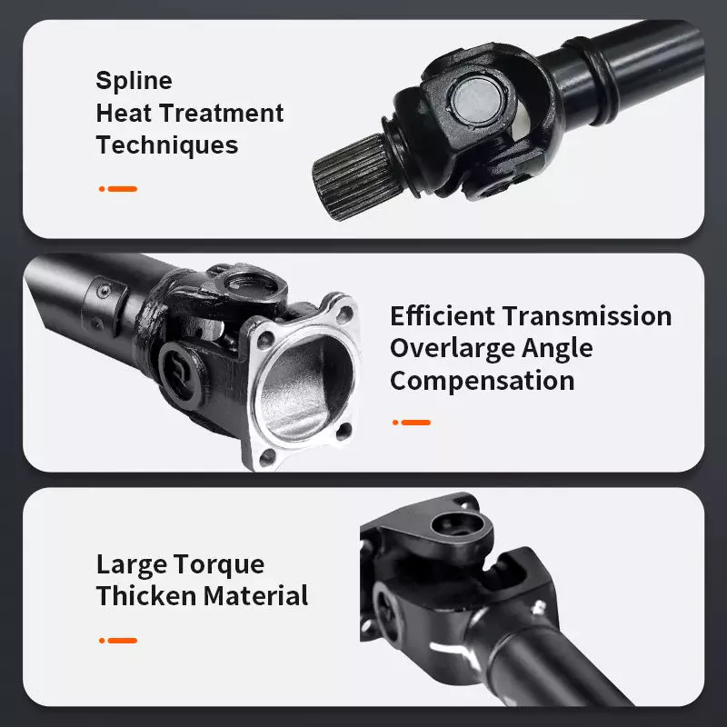
How do drive shafts contribute to the efficiency of vehicle propulsion and power transmission?
Drive shafts play a crucial role in the efficiency of vehicle propulsion and power transmission systems. They are responsible for transferring power from the engine or power source to the wheels or driven components. Here’s a detailed explanation of how drive shafts contribute to the efficiency of vehicle propulsion and power transmission:
1. Energieübertragung:
Drive shafts transmit power from the engine or power source to the wheels or driven components. By efficiently transferring rotational energy, drive shafts enable the vehicle to move forward or drive the machinery. The design and construction of drive shafts ensure minimal power loss during the transfer process, maximizing the efficiency of power transmission.
2. Torque Conversion:
Drive shafts can convert torque from the engine or power source to the wheels or driven components. Torque conversion is necessary to match the power characteristics of the engine with the requirements of the vehicle or machinery. Drive shafts with appropriate torque conversion capabilities ensure that the power delivered to the wheels is optimized for efficient propulsion and performance.
3. Gleichlaufgelenke (CV-Gelenke):
Many drive shafts incorporate Constant Velocity (CV) joints, which help maintain a constant speed and efficient power transmission, even when the driving and driven components are at different angles. CV joints allow for smooth power transfer and minimize vibration or power losses that may occur due to changing operating angles. By maintaining constant velocity, drive shafts contribute to efficient power transmission and improved overall vehicle performance.
4. Lightweight Construction:
Efficient drive shafts are often designed with lightweight materials, such as aluminum or composite materials. Lightweight construction reduces the rotational mass of the drive shaft, which results in lower inertia and improved efficiency. Reduced rotational mass enables the engine to accelerate and decelerate more quickly, allowing for better fuel efficiency and overall vehicle performance.
5. Minimized Friction:
Efficient drive shafts are engineered to minimize frictional losses during power transmission. They incorporate features such as high-quality bearings, low-friction seals, and proper lubrication to reduce energy losses caused by friction. By minimizing friction, drive shafts enhance power transmission efficiency and maximize the available power for propulsion or operating other machinery.
6. Balanced and Vibration-Free Operation:
Drive shafts undergo dynamic balancing during the manufacturing process to ensure smooth and vibration-free operation. Imbalances in the drive shaft can lead to power losses, increased wear, and vibrations that reduce overall efficiency. By balancing the drive shaft, it can spin evenly, minimizing vibrations and optimizing power transmission efficiency.
7. Maintenance and Regular Inspection:
Proper maintenance and regular inspection of drive shafts are essential for maintaining their efficiency. Regular lubrication, inspection of joints and components, and prompt repair or replacement of worn or damaged parts help ensure optimal power transmission efficiency. Well-maintained drive shafts operate with minimal friction, reduced power losses, and improved overall efficiency.
8. Integration with Efficient Transmission Systems:
Drive shafts work in conjunction with efficient transmission systems, such as manual, automatic, or continuously variable transmissions. These transmissions help optimize power delivery and gear ratios based on driving conditions and vehicle speed. By integrating with efficient transmission systems, drive shafts contribute to the overall efficiency of the vehicle propulsion and power transmission system.
9. Aerodynamic Considerations:
In some cases, drive shafts are designed with aerodynamic considerations in mind. Streamlined drive shafts, often used in high-performance or electric vehicles, minimize drag and air resistance to improve overall vehicle efficiency. By reducing aerodynamic drag, drive shafts contribute to the efficient propulsion and power transmission of the vehicle.
10. Optimized Length and Design:
Drive shafts are designed to have optimal lengths and designs to minimize energy losses. Excessive drive shaft length or improper design can introduce additional rotational mass, increase bending stresses, and result in energy losses. By optimizing the length and design, drive shafts maximize power transmission efficiency and contribute to improved overall vehicle efficiency.
Overall, drive shafts contribute to the efficiency of vehicle propulsion and power transmission through effective power transfer, torque conversion, utilization of CV joints, lightweight construction, minimized friction, balanced operation, regular maintenance, integration with efficient transmission systems, aerodynamic considerations, and optimized length and design. By ensuring efficient power delivery and minimizing energy losses, drive shafts play a significant role in enhancing the overall efficiency and performance of vehicles and machinery.
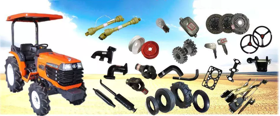
Gibt es Unterschiede in der Konstruktion der Antriebswelle für verschiedene Maschinentypen?
Ja, es gibt verschiedene Ausführungen von Antriebswellen, die auf die spezifischen Anforderungen unterschiedlicher Maschinentypen zugeschnitten sind. Die Konstruktion einer Antriebswelle wird von Faktoren wie Anwendung, Kraftübertragungsbedarf, Platzverhältnissen, Betriebsbedingungen und Art der angetriebenen Komponenten beeinflusst. Im Folgenden wird erläutert, wie sich Antriebswellen für verschiedene Maschinentypen unterscheiden können:
1. Anwendungen im Automobilbereich:
In der Automobilindustrie variieren die Konstruktionen von Antriebswellen je nach Fahrzeugkonfiguration. Fahrzeuge mit Hinterradantrieb verwenden typischerweise eine ein- oder zweiteilige Antriebswelle, die das Getriebe oder Verteilergetriebe mit dem Hinterachsdifferenzial verbindet. Fahrzeuge mit Vorderradantrieb nutzen häufig eine andere Konstruktion mit einer Antriebswelle, die in Kombination mit Gleichlaufgelenken (CV-Gelenken) die Kraft auf die Vorderräder überträgt. Fahrzeuge mit Allradantrieb können mehrere Antriebswellen besitzen, um die Kraft auf alle Räder zu verteilen. Länge, Durchmesser, Material und Gelenktypen können je nach Fahrzeugaufbau und Drehmomentanforderungen variieren.
2. Industriemaschinen:
Die Konstruktion von Antriebswellen für Industriemaschinen hängt von der jeweiligen Anwendung und den Anforderungen an die Kraftübertragung ab. In Fertigungsmaschinen wie Förderbändern, Pressen und rotierenden Anlagen sind Antriebswellen so ausgelegt, dass sie die Kraft effizient innerhalb der Maschine übertragen. Sie können flexible Gelenke aufweisen oder über eine Keilwellen- oder Passfederverbindung verfügen, um Fluchtungsfehler auszugleichen oder eine einfache Demontage zu ermöglichen. Die Abmessungen, Werkstoffe und die Verstärkung der Antriebswelle werden anhand des Drehmoments, der Drehzahl und der Betriebsbedingungen der Maschine ausgewählt.
3. Landwirtschaft und Ackerbau:
Landmaschinen wie Traktoren, Mähdrescher und Erntemaschinen benötigen häufig Antriebswellen, die hohen Drehmomenten und unterschiedlichen Betriebswinkeln standhalten. Diese Antriebswellen übertragen die Kraft vom Motor auf Anbaugeräte wie Mähwerke, Ballenpressen, Bodenfräsen und Erntemaschinen. Sie können teleskopierbare Abschnitte für variable Längen, flexible Gelenke zum Ausgleich von Fehlausrichtungen im Betrieb und Schutzvorrichtungen zum Schutz vor Verheddern mit Erntegut oder Fremdkörpern aufweisen.
4. Bau- und Schwermaschinen:
Baumaschinen und schwere Geräte wie Bagger, Lader, Planierraupen und Kräne benötigen robuste Antriebswellen, die auch unter anspruchsvollen Bedingungen Kraft übertragen können. Diese Antriebswellen weisen oft größere Durchmesser und dickere Wände auf, um hohen Drehmomenten standzuhalten. Sie können Kreuzgelenke oder Gleichlaufgelenke (CV-Gelenke) beinhalten, um Betriebswinkel zu ermöglichen und Stöße und Vibrationen zu absorbieren. Antriebswellen dieser Kategorie können zudem zusätzliche Verstärkungen aufweisen, um den rauen Umgebungsbedingungen und den hohen Belastungen im Bau- und Erdbau standzuhalten.
5. Anwendungen im maritimen Bereich:
Antriebswellen für Schiffsanwendungen sind speziell darauf ausgelegt, den korrosiven Einflüssen von Meerwasser und den hohen Drehmomentbelastungen in Schiffsantriebssystemen standzuhalten. Sie bestehen typischerweise aus Edelstahl oder anderen korrosionsbeständigen Werkstoffen. Flexible Kupplungen oder Dämpfungselemente reduzieren Vibrationen und minimieren die Auswirkungen von Fluchtungsfehlern. Bei der Konstruktion von Schiffsantriebswellen werden zudem Faktoren wie Wellenlänge, Durchmesser und Lager berücksichtigt, um eine zuverlässige Kraftübertragung in Schiffen zu gewährleisten.
6. Bergbau- und Gewinnungsausrüstung:
In der Bergbauindustrie werden Antriebswellen in schweren Maschinen und Geräten wie Muldenkippern, Baggern und Bohranlagen eingesetzt. Diese Antriebswellen müssen extrem hohen Drehmomenten und rauen Betriebsbedingungen standhalten. Antriebswellen für den Bergbau zeichnen sich häufig durch größere Durchmesser, dickere Wände und spezielle Werkstoffe wie legierten Stahl oder Verbundwerkstoffe aus. Sie können Kreuzgelenke oder Gleichlaufgelenke zur Bewältigung von Betriebswinkeln aufweisen und sind abrieb- und verschleißfest konstruiert.
Diese Beispiele verdeutlichen die Unterschiede in der Konstruktion von Antriebswellen für verschiedene Maschinentypen. Bei der Konstruktion werden Faktoren wie Leistungsbedarf, Betriebsbedingungen, Platzverhältnisse, Ausrichtungsanforderungen und die spezifischen Anforderungen der jeweiligen Maschine oder Branche berücksichtigt. Durch die Anpassung der Antriebswelle an die individuellen Anforderungen jeder Anwendung lassen sich optimale Kraftübertragungseffizienz und Zuverlässigkeit erzielen.


editor by CX 2024-04-22