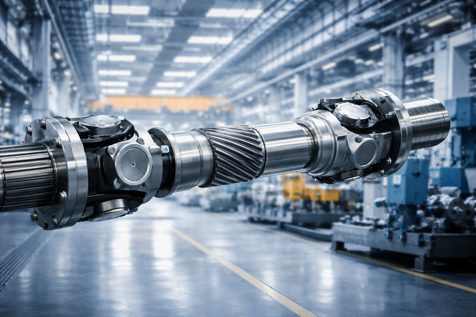
Powering the “Heavy Tanks” of the Sea
From the Port of Felixstowe to offshore wind farm construction in the North Sea, our drive shafts keep the cutter heads turning.
Core Technical Brief: This comprehensive engineering resource provides an in-depth analysis of the critical role of industrial universal joints in cutter suction dredgers (CSDs). We analyze the different kinematic characteristics of inboard drive and ladder drive systems, with a focus on the 45° angle compensation required for deep-water dredging (-30 meters). Furthermore, we detail the metallurgical and sealing requirements necessary to withstand an impact coefficient of 3.0 and the corrosive marine environment of C5-M commonly found in British coastal waters.
The Engineering Challenge: Dredging in the UK Maritime Environment
Cutter suction dredgers (CSDs) are often hailed as the “heavy tanks” of the dredging industry. Unlike trailing suction hopper dredgers, CSDs actively cut through the seabed, frequently navigating the complex geological conditions common to the British coastline, including compacted sand, clay, and even rock, from the chalk formations of Dover to the granite basement of Scotland.
The operating environment is extremely harsh. The transmission system must not only transmit torque but also withstand the elastic deformation of the hull, extreme sea states (up to sea state 5 during navigation), and the continuous erosion from salt spray and sediment. Industrial universal joints act as “flexible fuses,” serving as the primary torque channel between the prime mover (diesel engine or electric motor) and the working machinery (cutter suction dredger or dredging pump).
👨🔧 Engineer’s Note from Bury St Edmunds HQ:
“In the past 15 years of service to dredging fleets in the Thames Estuary and Humber, we have found that standard industrial shafts can fail catastrophically within months. Hull arching/sinking (which can cause deviations on the order of centimeters) and the ‘stall torque’ impact when the cutterhead hits the bedrock require shafts to be designed very differently from those used on land. It’s not just about torque, but also about torsional strength.”
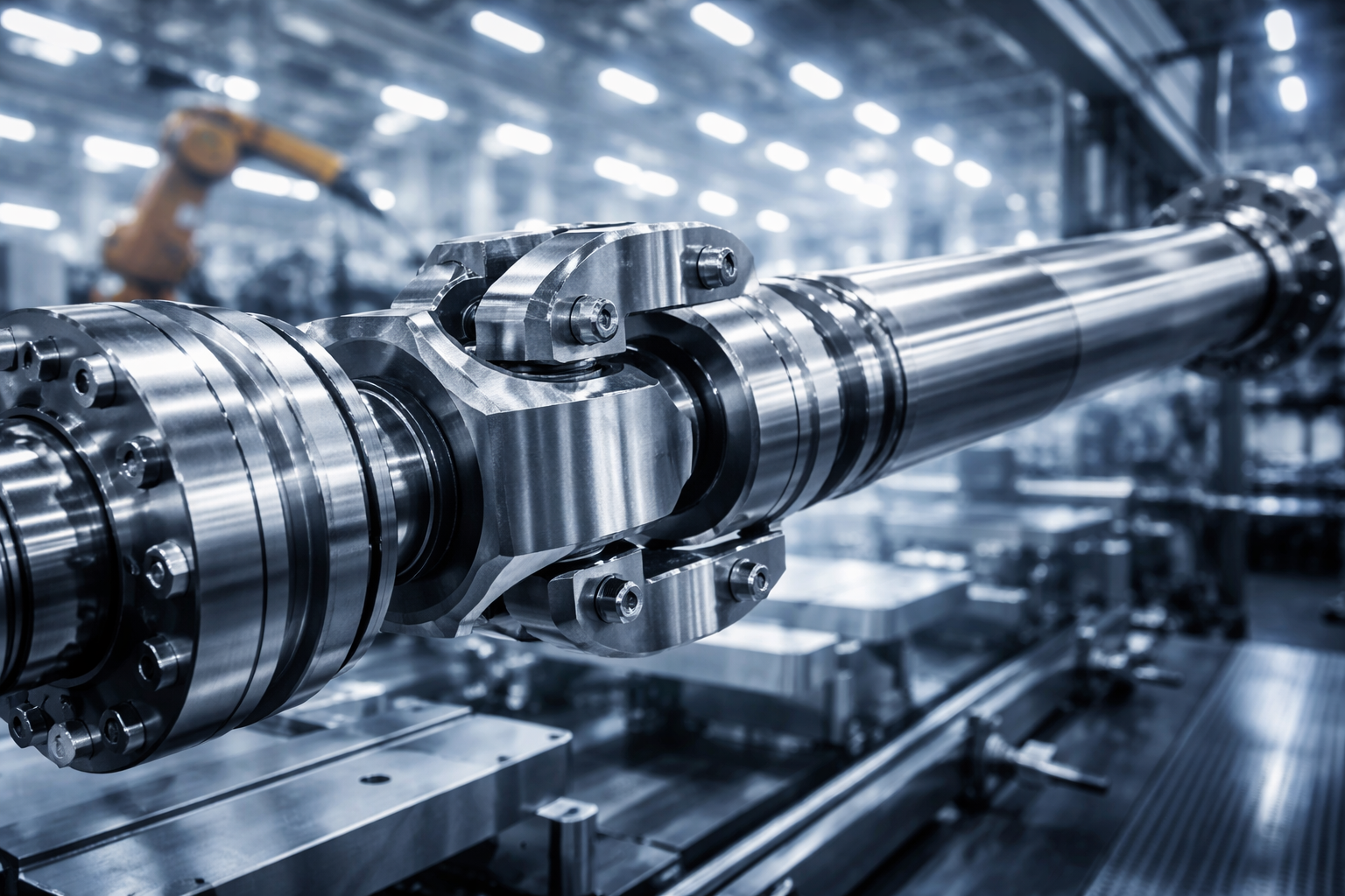
Deep Dive: Cutter Head Drive Systems
The cutter head is the business end of the CSD. The drive system used to power this head defines the dredging capability. There are two primary configurations, each presenting unique challenges for the cardan shaft.
Inboard Drive Configuration: The Geometry Problem
In this setup, the heavy electric motor or diesel engine is located safely inside the main hull. Power is transmitted through a long shaft line that passes through the ladder trunnion (pivot point) to the gearbox at the cutter head.
- Mechanical Component: Ladder Trunnion Cardan Shaft.
- The Kinematic Challenge: As the ladder is lowered to reach maximum dredging depths (often -25m to -30m), the angle between the hull-mounted shaft and the ladder-mounted gearbox changes drastically. This angle can exceed 45 degrees.
- The Solution: A standard single universal joint cannot accommodate this angle without inducing severe non-uniform velocity (vibration). We engineer solutions using Wide Angle Joints or complex multi-joint linkage mechanisms. These ensure that despite the steep angle, the angular velocity transmission remains constant, preventing torsional vibration from shattering the gearbox teeth.
Ladder Mounted Drive: The Submersible Challenge
Alternatively, the motor (often hydraulic or electric) is mounted directly onto the ladder, sometimes even submerged underwater.
- Mechanical Component: Submersible Motor Coupling Shaft.
- The Environmental Challenge: This shaft operates in the splash zone or completely underwater. It is constantly bombarded by a slurry of sand, rock, and saltwater.
- The Solution:
- Oil-Filled Boots: Unlike standard grease seals, we utilise oil-filled, pressurised boots that maintain a positive pressure inside the cross bearing. This prevents the ingress of abrasive silt.
- Surface Treatment: The yokes and tubes undergo a specialized marine coating process (detailed in Section 4) to resist pitting corrosion.
Handling Shock Loads: The Stall Torque Scenario
When a cutter head digs into unexpected hard rock or old seabed infrastructure (common in historic UK ports), the rotation can stop instantly. This creates a “Stall Torque” event, sending a shockwave back through the drivetrain.
Our shafts are designed with a Shock Factor (SF) of 2.5 to 3.0. Furthermore, we integrate protection devices:
- Shear Pin Couplings: A sacrificial pin designed to snap at a precise load, disconnecting the drive before the expensive shaft or gearbox breaks.
- Friction Clutches: Capable of slipping during momentary overloads and re-engaging automatically.
Dredge Pump Drive Analysis
While the cutter head breaks the soil, the dredge pump transports it. The impeller inside the pump also faces risks of jamming from large rocks or debris.
- Component: Dredge Pump Drive Shaft.
- Key Feature – Quick Release: Pump blockages happen. To minimize downtime, our shafts feature a Quick Release Flange design. This allows maintenance crews to disconnect the power transmission rapidly, granting access to the pump housing for clearing blockages or changing impellers without moving the heavy motor or pump casing.
Technical Specifications & Engineering Parameters
At UK pto-drive-shafts.com Co.,Ltd., we engineer our shafts to exceed standard industrial requirements. Below is the specification matrix for our Marine Dredging Series.
| Parameter | Standard Specification | High-Performance Marine Spec (UK pto-drive-shafts.com Co.,Ltd) |
|---|---|---|
| Torque Range (Rated) | 5 kNm – 50 kNm | 20 kNm – 350 kNm+ |
| Max. Deflection Angle | 15° – 25° | up to 45° (Wide Angle Design) |
| Dynamic Balancing | G16 (ISO 1940) | G6.3 (Precision Marine) |
| Core Material | Standard Carbon Steel | 42CrMo4 Alloy Steel / 316L Stainless Options |
| Spline Coating | Phosphating | Rilsan® / Molybdenum Disulfide (MoS2) |
| Sealing System | Standard Rubber Lip | Multi-Stage Labyrinth & Oil-Filled Boots |
| Corrosion Protection | C3 Industrial Paint | C5-M Marine (ISO 12944) – >320μm DFT |
Note: Parameters may vary based on specific vessel design. Please consult our technical drawings for exact fitment.
UK Market Focus: Compliance and Local Adaptation
Operating in UK waters requires adherence to strict maritime safety and environmental standards. Our products are designed to align with:
- Lloyd’s Register & DNV GL: Our shafts meet the material traceability and fatigue strength requirements set by major classification societies common in the UK marine sector.
- UK Health and Safety Executive (HSE): We prioritize guard safety. All rotating parts are enclosed in heavy-duty, non-rotating guards to prevent entanglement, a critical compliance point for UK operators.
- Local Supply Chain: Located in Bury St Edmunds, Suffolk, we are strategically positioned near major east coast ports like Felixstowe and Harwich. This ensures that replacement parts (U-joints, flange yokes) can be dispatched same-day to minimize demurrage costs for dredging contractors.
Brand Compatibility and Replacement Strategy
Seamless Retrofitting and Upgrades
We understand that many central differentials (CSDs) operating in the UK are built by Dutch or Belgian shipyards and may be equipped with original equipment shafts from manufacturers such as GKN, Voith, or Centa. Our engineering team has established a comprehensive cross-reference database.
We can provide replacement parts that perfectly match the flange specifications (DIN/SAE/keyways) and torque ratings of these brands’ shafts, and often feature more advanced sealing technologies, making them more suitable for older vessels.
*Disclaimer: All manufacturer names, symbols, and descriptions (e.g., GKN, Voith) are used for reference purposes only. UK pto-drive-shafts.com Co.,Ltd. is an independent manufacturer and is not affiliated with these brands. Our products are high-quality aftermarket replacements manufactured by UK pto-drive-shafts.com Co.,Ltd.
Installation & Maintenance: Ensuring Longevity
Protocol: Submersible Shaft Installation
Installing a shaft that will be submerged requires meticulous attention to detail.
- Clean the Flanges: Ensure the mating surfaces of the gearbox and motor flanges are free of rust, paint, or grease. Even a 0.1mm particle can cause run-out.
- Check Phasing: For shafts with slip splines, ensure the yokes are aligned (in phase) to prevent vibration. Our shafts come marked, but this must be verified.
- Torque to Spec: Use calibrated torque wrenches for all flange bolts. Use marine-grade thread locker.
- Seal Integrity Check: Before submerging, pressure test the boot seals if applicable. Ensure the air release valve is closed after greasing.
- Laser Alignment: Where possible, perform a laser alignment of the drivetrain. Remember to account for the “soft foot” of the motor mounting.
Ready to Upgrade Your Dredging Fleet?
Don’t let a broken shaft halt your project in the middle of the channel. Trust the UK experts in heavy-duty marine transmission.
UK pto-drive-shafts.com Co.,Ltd.
Address: Bury St Edmunds, Suffolk IP32 7LX, UK
Email: [email protected]
edit by gzl


